Sentex SW2200 Manual de usuario

Doc 01-G0181
Rev A
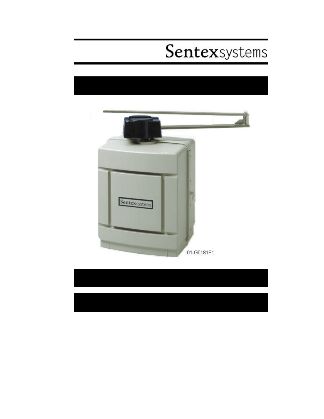
Installation Instructions
Swing Gate Operator
Model SW2200

2Contents
Doc 01-G0181
Rev A
Contents
Safety Information______________________________________________ 3
Definitions _____________________________________________________________ 3
Important Safety Information _______________________________________________ 3
Classifications___________________________________________________________ 5
Specifications__________________________________________________ 6
Mechanical _____________________________________________________________ 6
Electrical_______________________________________________________________ 6
Site Preparation _______________________________________________ 10
Pad Mounting __________________________________________________________ 10
Installation___________________________________________________ 11
Mechanical ____________________________________________________________ 11
Electrical______________________________________________________________ 13
Basic Setup and Device Connections ______________________________ 14
Setup ______________________________________________________________ 14
Device Connections _____________________________________________________ 16
Operator Programming Menu (LCD Screen)________________________ 17
Definitions and Options __________________________________________________ 17
Troubleshooting_______________________________________________ 19
Diagnostic Screen_______________________________________________________ 19
Entrapment Adjustment __________________________________________________ 20
No Position or Speed ____________________________________________________ 20
Replacement Parts Assembled____________________________________ 21
Parts List______________________________________________________________ 22
Maintenance _________________________________________________ 23
Cold Weather Operation__________________________________________________ 23
Appendix ____________________________________________________ 24
Wire Sizes and Distances _________________________________________________ 24
Non-Standard Installation_________________________________________________ 24

Safety Information 3
Doc 01-G0181
Rev A
Safety Information
Definitions
ENTRAPMENT
The condition when an object is
caught or held in a position that
increases the risk
of injury.
CAUTION
Indicates a potentially hazardous situation
which, if not avoided, may result in minor
or moderate injury. It may also be used to
alert against unsafe practices.
DANGER
Indicates an imminently hazardous
situation which, if not avoided, will
result in death or serious injury.
This signal word is to be limited to
the most extreme situations.
WARNING
Indicates a potentially hazardous
situation which, if not avoided,
could result in death or serious
injury.
NOTE
DANGER or WARNING should not
be considered for property damage
accidents unless personal injury risk
is appropriate to these levels is also
involved.
CAUTION is only permitted for
property damage accidents.
PASSPOINT
A reference point to set/find open/close
limits. When gate reaches passpoint, PP
LED blinks.
Important Safety Information
WARNING
Read and follow all instructions.
TO REDUCE THE RISK OF INJURY OR DEATH . . .
Never let children operate or play with gate controls. Keep the remote
control away from children.
Always keep people and objects away from the gate. No one should cross
the path of the moving gate.
Test the gate operator monthly. The gate must reverse when any safety
device is activated. After adjusting or setting limits of an operator, retest the
gate operator. Failure to adjust and retest the gate operator properly
can increase the risk of injury or death.
Use the emergency release only when the gate is not moving.
Keep gates properly maintained. Read the owner’s manual. Have a
qualified service technician make repairs to gate hardware.
The entrance is for vehicles only. Pedestrians must use separate entrance.
Save these instructions!

4Safety Information
Doc 01-G0181
Rev A
INSTALL THE GATE OPERATOR ONLY IF . . .
The operator is appropriate for the construction of the gate and the usage
class of the gate.
All openings are guarded or screened to prevent access by arms or legs
through openings anywhere in the gate.
All exposed pinch points are eliminated or guarded.
The operator is intended only for installation on gates used for vehicles.
Pedestrians must be provided with a separate access opening.
NOTES: The gate must be installed in a location so that sufficient
clearance is provided between the gate and adjacent structures when
opening and closing to reduce the risk of entrapment. Swinging gates
should not open into public access areas.
The gate must be properly installed and work feely in both directions prior
to the installation of the gate operator.
NON-CONTACT SENSORS (E.G., PHOTOCELL)
Read the following for gate operators utilizing non-contact sensors:
See instructions on the placement of non-contact sensors for each type of
application.
Exercise care to reduce the likelihood of nuisance tripping.
To prevent gate entrapment, install non-contact sensors on both sides of
the gate to cover the gate perimeter during closing and opening.
LOOP VEHICLE DETECTORS
Read the following for gate operators utilizing loop vehicle detectors:
WARNING
Loop Detectors do not provide protection for people! Loops should
only be used for vehicular control.
Follow manufacturers instructions for loop installation.
Gates can be made of metal and will therefore react with the loop system,
creating false tripping. Please note loop manufacturer’s recommendations
for minimum gate clearance.
Loop sense wiring must be secure within its ground track. Loose wiring will
cause false triggering. Leader wires from the loop track to the detector
must be wrapped 5 times per foot minimum to prevent false tripping.

Safety Information 5
Doc 01-G0181
Rev A
Classifications
CLASS I
Residential Vehicular Gate Operator
A vehicular gate operator (or system) intended for use in a home or one-to-four
single family dwelling, or a garage or parking area associated therewith. Required
additional equipment—Type B1 non-contact sensor.
CLASS II
Commercial/General Access Vehicular Gate Operator
A vehicular gate operator (or system) intended for use in a commercial location or
building such as a multi-family housing unit (five or more single family units) hotel,
garages, retail store, or other building servicing the general public. Required
additional equipment—Type B1 non-contact sensor, or Type E—an audio alarm.
CLASS III
Industrial/Limited Access Vehicular Gate Operator
A vehicular gate operator (or system) intended for use in an industrial location or
building such as a factory or loading dock area, or other locations not intended to
service the general public.
CLASS IV
Restricted Access Vehicular Gate Operator
A vehicular gate operator (or system) intended for use in a guarded industrial
location or building such as an airport security area or other restricted access
locations not servicing the general public, in which unauthorized access is
prevented via supervision by security personnel.

6Specifications
Doc 01-G0181
Rev A
Specifications
Mechanical
GENERAL SPECIFICATIONS
Overall Size Weight
19”L x 23”W x 31”H 190 Pounds
Table 1
GENERAL CONSTRUCTION
Electroplated, welded steel frame with
a dual gearbox reduction of 600:1 and
an ultimate strength of 2,000 foot
pound. The cover is UV durable
plastic.
GATE CAPACITY
This operator is designed for maximum
size gates. In general, the operator may
work with any gate below 1000 pounds
and 22 feet, with low wind resistance,
sturdy construction, and good hinges.
Electrical
Always use a qualified electrician and follow your local construction codes when
connecting power. General guidelines are:
Line voltage required is 115 VAC
(10% [103-127]) single phase. Wire size, accessory power (18-gauge
recommended).
Line amperage Required 15 Amps
Max. Device controls - any insulated wire can
be used (18-24 gauge recommended).
Wire size, operator power – see
Wire Sizes and Distances on
page 24.
NOTE: The operator is permanently
wired; it does not use a grounding plug.
ELECTRICAL BOX
See Figure 1. Stamped aluminum housing for the processor, motor VFD drive, and
front panel PCB's. For factory repair, the complete panel can be quickly removed
and replaced.
CAUTION
Do not repair or open box!
There is a potential shock
hazard from the High Voltage
capacitor! Danger exists even
when power is disconnected!

Specifications 7
Doc 01-G0181
Rev A
Figure 1
PROGRAMMING
Programming is accomplished with a 5 button, 2 LED membrane switch located on
top of the control box. Programming instructions are presented on a 2 row, 16
character LCD screen (see Figure 2).
Sentex
systems
01-16169F1
Figure 2
DEVICE CONNECTIONS
Connections are made to the lower half (exposed half) of the front panel PCB.
Provisions are made for:
J2 – Safety edge open (trailing edge contact
sensor); N/O & N/C J8 – Hold open (no timer); Single Button
J3 – Safety edge close (leading edge contact
sensor); N/O & N/C J9 – Photo eye (non-contact sensor); N/O
& N/C Contacts
J4 – 3 loop detectors JP5, JP6, JP7, & JP8 – Output relays for
lights, etc.
J5 – Close; Open w/ Timer JP5, JP6, JP7 – Master/Slave connections
J6 – Not Used
J7 – Stop (required N/C connection)
JP9 – 24 VDC power
JP12 – 24 VAC power
JP14 – 115 VAC power

8Specifications
Doc 01-G0181
Rev A
01-20211F1
(NO)
CLOSE
(NO)
OPENW/
TIMER
Figure 3
MASTER/SLAVE CONNECTIONS (OPTION)
Sentex Systems recommends18-20 gauge wire for the minimal wattage required to
run a pair in master/slave setups.
WHITE
BLACK
CLOSE RELAY
STOP RELAY
OPEN RELAY
MASTER
RED GREEN
SLAVE
J7
STOP
J8
J5
(NC)
STOP
J8
HOLDSINGLE
OPENBUTTON
01-20211F2
COM
COM
COM
COM
COM
COM
Figure 4

Specifications 9
Doc 01-G0181
Rev A
FULL BATTERY BACKUP (OPTION)
24 hours continuous operation with normal use of accessory! This is the only
operator offered with transparent battery backup.

Site Preparation 10
Doc 01-G0181
Rev A
Site Preparation
Pad Mounting
For pad mounting instructions, perform the steps below and refer to the Figures below.
AVAILABLE CABLE
ENTRY ZONE
(Keep All Conduits
Within Shaded Area)
4.50
1.37
1.50
3.25
0.75
TYP. 13.50
15.00
21.00
1/2” ANCHOR BOLTS
FOUR (4) PLACES TYP.
COVER
OUTLINE
01-G0181F5
Figure 5
1”
6” min.
01-G0181F6
Figure 6
1Excavate to the depth required by
local code or below frost line.
2Situate pad according to Figure 7.
3Using a license and qualified
electrician, route wiring for operator
power and controls prior to pouring
concrete. Situate conduit on pad
as shown in Figure 5.
4Pour concrete ensuring that the
pad is level and, 2" to 4" above
ground line.
5Sink (4) 1/2" x 6" minimum length
L-bolts (not supplied) as detailed in
Figure 6and Figure 7. The bolts
should protrude 1" above the pad.
The shipping crate bottom may be
used as a bolt pattern template.
6Allow concrete to set for 2 days
before installing operator.
7If there is existing concrete on the
site, use 1/2" anchor bolts (not
supplied) to secure the unit. If
needed, use washers to shim the
operator level with the gate.
NOTE: Local Codes - This
manual does not supersede
local codes for construction,
and was written to be used by
a qualified and licensed
electrician.
For non-standard installations or
retrofit applications, see Non-
Standard Installation on page 24
for instructions.
GATE
HINGE PIN
COLUMN FENCE
21.00
13.50
OPERATOR
SHAFT
LOCATION
CABLE ENTRY
ZONES
ANCHOR BOLT
LOCATION
4.75
35.75
40.50
7.50
01-G0181F7
Figure 7
Tabla de contenidos
Otros manuales de Abridor de puerta de Sentex


