sensotran, s.l.
GAS SENSORS AND TRANSDUCERS
1. Introduction
The GasVisor has 3 alarm levels with independent volt-free contacts, as well as a
fault relay. Bus relay expansion boards can be fitted as an option.
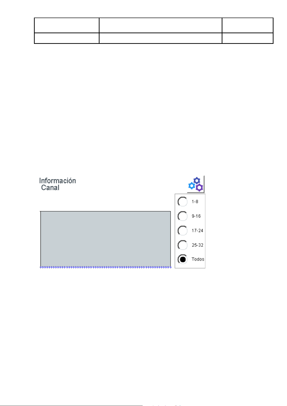
It also has a 4.7" backlit touch screen display to show the concentration of the
detectors, as well as the alarm outputs.
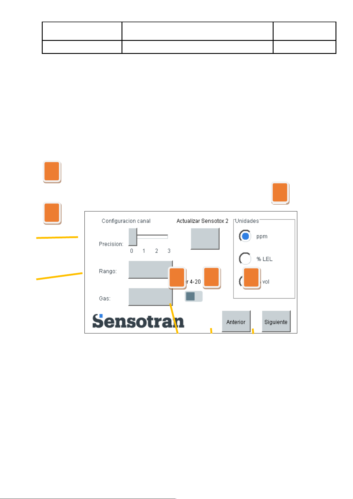
Measurement ranges in % of LEL, % volume and ppm of the programmed toxic gas,
where these can be placed interchangeably and giving the concentration in the
installed detector units.
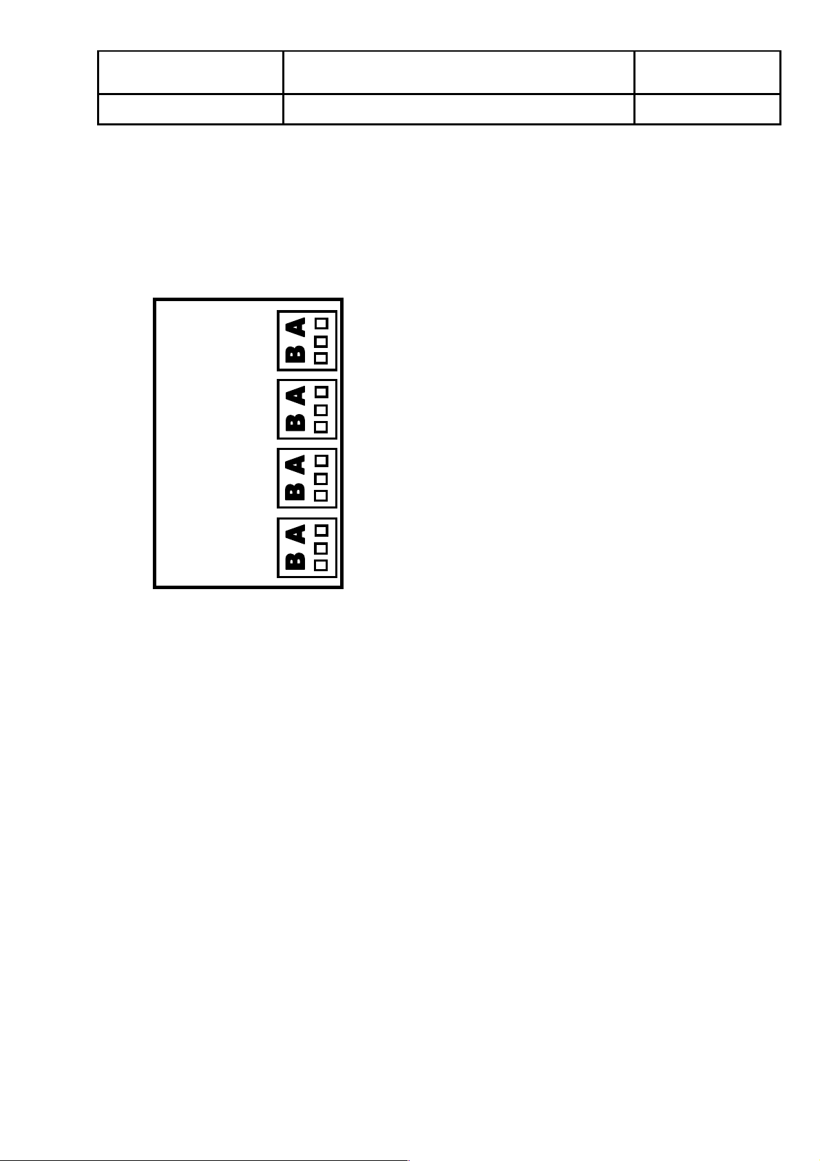
2. Wiring
Connect the power supply, at between 85 and 280 VAC / 50 Hz, to the JP7 connector
as shown in Figure 1.
The sensors must be connected to S1, S2, S3, S4, S5, S6, S7 and S8, where S1 is
channel 1, S2 is channel 2, S3 is channel 3, S4 is channel 4, S5 is channel 5, S6 is
channel 6, S7 is channel 7 and S8 is channel 8. Channels S4, S5, S6, S7 and S8 are
optional.
The alarm relay outputs are to be connected to RL1 for Alarm 1, RL2 Alarm 2, RL3
Alarm 3 and RL4 for the Fault relay.
Mains power supply (80-280 V, 50 Hz)
Mains power supply (80-280 V, 50 Hz)
Analog sensor 6 (4-20 mA)
Analog sensor 1 (4-20 mA)
Analog sensor 7 (4-20 mA)
Analog sensor 2 (4-20 mA)
Analog sensor 8 (4-20 mA)
Alarm relay contact 1 (NO)
Alarm relay contact 1 (NO)
Analog sensor 3 (4-20 mA)
Alarm relay contact 2 (NO)
Alarm relay contact 2 (NO)
Alarm relay contact 3 (NO)
Analog sensor 4 (4-20 mA)
Alarm relay contact 4 (NO)
Analog sensor 5 (4-20 mA)