Seagate Technology CTT 8000 Manual de usuario

CTT 8000
Internal SCSI
Minicartridge
Drive

FCC Notice
This equipment generates and uses radio frequency energy and, if not
installed and used in strict accordance with the manufacturer's
instructions, may cause interference to radio and television reception
which could void the user's authority to operate the equipment. It has
been tested and found to comply with the limits for a Class B digital device
pursuant to Part 15 of FCC Rules, which are designed to provide
reasonable protection against such interference in a residential
installation. However, there is no guarantee that interference will not
occur in a particular installation. If interference does occur, try to correct
it by taking one or more of the following measures:
λReorient or relocate the receiving antenna.
λIncrease the separation between the computer and the receiver.
λConnect the computer into an outlet on a circuit different from
that to which the receiver is connected.
λConsult the dealer or an experienced radio/television
technician for help.
Further, this equipment complies with the limits for Class B digital
apparatus in accordance with Canadian Radio Interference
Regulations.
Cet appareil numérique de la classe B est conforme au Règlement
sur brouillage radioélectrique, C. R. C., ch. 1374.
Seagate and the Seagate logo are registered trademarks of Seagate
Technology. All other trademarks mentioned in this manual are the
property of their respective owners.
Copyright 1996, Seagate Technology. All rights reserved. No part
of this publication may be reproduced, stored in a retrieval system,
or transmitted, in any form or by any means, electronic, mechanical,
photocopying, recording or otherwise, without prior written
permission from Seagate Technology. Product features and
specifications described in this guide are subject to change without
notification.
Document No. 10002473-003
Stocking No. 601-085

Installation Manual Page 1
Introduction
The Seagate internal CTT8000 SCSI minicartridge drive is
a fully integrated system that offers 4 Gigabytes (GB) of
native storage capacity with up to 8 GB of storage using
software data compression and the 3M Travan cartridge.
The drive provides a backup rate of up to 30
megabytes/minute (MB/min) without data compression in
a best case scenario with the system optimized1. Under
less than optimum conditions, transfer rates might range
from 18 to 28 MB/min. Given sufficient system resources
and compressible data structures, nominal transfer rates
of up to 60 MB/min can be observed using software data
compression (assumes 2:1 compression ratio).
The CTT8000 drive reads and writes the QIC-3080MC and
QIC-3095MC formats. The drive also provides a backward
read capability by reading the QIC 80,
QIC-3010, and QIC-3020 formats.
Seagate FastSenseTM enables the drive to automatically
sense the fastest supportable data transfer rate of the host
system and then chooses a transfer speed of either 600,
450, or 300 kilobytes/second (KB/sec). The drive meets
QIC-3080 and QIC-3095 specifications.
The drive unit installs internal to the computer in a one-
inch height 3.5-inch or half-height 5.25-inch drive bay.
Figures 1 and 2 illustrate the drive models.
1Actual performance on your system might vary and is dependent on the
system resources available and the structure and type of data compressed.

Internal SCSI Minicartridge Drive
Page 2 Installation Manual
Figure 1
SCSI Travan Minicartridge Drive (3.5-Inch Mount)
6.19" (157.2mm)
1.00"
(25.4mm)
DRIVE ACTIVE
(GREEN)
4.00"
(102.6mm)
0.157" (4mm)
4.00" (101.6mm)
Figure 2
SCSI Travan Minicartridge Drive (5.25-Inch
Mount)
1.685"
(42.8mm)
5.87"
(149.0mm)
0.20" (5.0mm)
0.86" (21.8mm)
5.76" (146.4mm)5.49" (139.4mm)
DRIVE ACTIVE
(GREEN)

Internal SCSI Minicartridge Drives
Installation Manual Page 3
Before You Begin
Keep the following guidelines in mind as you install the
unit:
λTo protect the drive from static electricity, DO NOT
remove it from the anti-static bag until you are
ready to install it.
λBefore you remove the drive from the anti-static bag,
touch a metal or grounded surface to discharge any
static electricity buildup from your body.
!Caution: If you touch static-sensitive parts of
the drive, such as the printed circuit board, and
discharge static electricity, the components may
be damaged.
λHold the drive by its edges only and avoid direct
contact with any printed circuit board exposed.
λLay the drive only on top of the anti-static bag or
return it to the bag when you need to lay it down.
Cabling and Connectors
The drive provides standard, single-ended SCSI
transmission. ANSI SCSI standards specify the technical
requirements for correctly cabling and connecting single-
ended devices.
Either 50-pin flat cable or 25-signal twisted-pair cable
with a maximum length of 6 meters (19 feet) may be used
to connect the drive to its SCSI host adapter output. If
twisted-pair cabling is used, connect the twisted pairs to
physically opposing contacts on the connector.

Internal SCSI Minicartridge Drive
Page 4 Installation Manual
Single-Ended SCSI Connector
The internal drive provides a 50-pin, right-angle, dual-row
connector on the main PCB at the rear of the unit.
Configuring the Drive
The drive mounts internal to the computer in either a 3.5-
inch by one-inch space or in a 5.25-inch half-high space
with the use of mounting rails and a surrounding bezel.
Three simple steps make up the installation procedure:
1. Configure jumpers.
2. Mount the drive unit.
3. Complete the power and interface connections.
The installation procedure is the same for both models
except physically mounting the unit in the computer.
After you configure the jumpers and decide whether or not
you need to add terminators, follow the steps provided for
the size of enclosure into which you are mounting the
drive.

Internal SCSI Minicartridge Drives
Installation Manual Page 5
Configuring Jumpers and Terminators
Figure 3 illustrates the location of the jumpers on the
bottom of the drive.
Figure 3
Location of Jumpers for Drive
SCSI
CONNECTOR
SCSI
PIN 1
POWER
CONNECTOR
NOTE:
Bottom of drive shown.
JUMPER
BLOCK
PIN 1
The following settings should be checked prior to
installation:
lSCSI ID
Note: Figure 4 shows the jumper configurations for
the various SCSI device addresses (IDs) and for the
other options.
lParity
lTerminator power
lTermination
Use the jumpers to set the SCSI device address. You can
also enable parity and enable terminator power by jumper
placements. SCSI terminators must be installed for the
last device on the SCSI bus.
Internal SCSI Minicartridge Drive
Page 6 Installation Manual
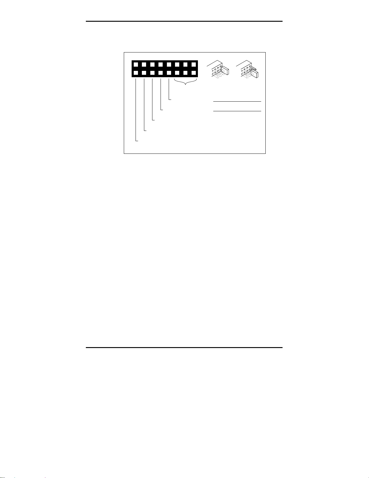
Figure 4
Jumper Configurations
10
9
6 4
3
2
1
12
11
14
13
16
15
8
SCSI ID
PARITY ENABLED
JUMPER 7-8 ON
RESERVED
RESERVED
ACTIVE TERMINATION
JUMPER 13-14 ON
TERMINATOR POWER ENABLED
JUMPER 15-16 ON
JUMPER ON JUMPER OFF
PIN PIN PIN SCSI
ID
531
642
OFF OFF 0OFF
ON OFF 1OFF
OFF ON 2OFF
ON ON 3OFF
OFF OFF 4ON
ON OFF 5ON
OFF ON 6ON
ON ON 7ON
75
Notes: In Figure 4, ON means that the jumper shunt
is placed over the two vertical pins. OFF means that
the jumper shunt is removed from the two vertical
pins (or hanging over only one of the pins).
The drive must be turned OFF; then, ON in order for
the jumper placements to take effect, or a SCSI Bus
Reset must be received.
If the default address setting ID is correct for your system,
and you do not choose to change any other options, go to
the following section that explains how to install the drive
unit.
If you need to change any default settings, refer to
Figure 4 and the appropriate following section; make the
changes and then go to the following section that explains
how to install the drive unit.

Internal SCSI Minicartridge Drives
Installation Manual Page 7
SCSI Device Address Jumpers
Be sure that no other device on the SCSI bus has the same
SCSI address.
Figure 4 shows the jumper placements for the various
SCSI ID choices.
Parity
To enable parity, place a jumper shunt over the two
pins7 and 8as shown in Figure 4. Be sure the jumper
shunt is firmly in place.
SCSI Terminator Enable
The last device on the SCSI bus must have termination.
Figure 5 illustrates the termination for two daisy-chain
configurations.
Figure 5
Daisy-Chain Configurations
SCSI Card Tape Drive SCSI
Device
Terminated Not
Terminated Terminated
SCSI Card Tape Drive
SCSI
Device
Terminated Not
Terminated Terminated
1
2
The CTT8000 supports active termination and does not
require the use of terminating resistor packs.

Internal SCSI Minicartridge Drive
Page 8 Installation Manual
Terminator Power Enabled
Terminator power (+5-volt) is enabled by default.
!Caution: If the jumper is installed, be careful
not to short the TERMPWR signal to ground.
The drive contains a terminator power fuse to prevent
damage to drive components in case the terminator power
is shorted. If terminator power is enabled and the SCSI
cable is connected upside down for example, this fuse may
blow to prevent damage to the drive itself. In that case,
return the drive to an authorized repair facility.
Mounting the Drive Unit
The internal drive can be installed in a one-inch high by
3.5-inch form factor or in a half-high by 5.25-inch form
factor (with rails). The drive can be installed in three
different orientations: one horizontally (LED to the left)
and two vertically (LED up and down).
The following section provides directions for mounting the
drive in either a 3.5-inch enclosure or in a 5.25-inch
enclosure.
Installing the Drive
The following steps guide you through installing the
internal drive.
!Caution: Turn off your computer before you
begin the installation. Failure to do so might
result in damage to your equipment or electrical
shock to you.
Note: Because computer models vary between
manufacturers, refer to your computer manual for
specific installation instructions.
Otros manuales para CTT 8000
1
Tabla de contenidos
Otros manuales de Accionamiento de CC de Seagate Technology


Manuales populares de Accionamiento de CC de otras marcas

Vincent Associates
Vincent Associates UNIBLITZ ED12DSS Manual de usuario

EKSMA OPTICS
EKSMA OPTICS DQ-100-4 Manual de lista de piezas

Chamberlain Garog
Chamberlain Garog D Series Manual de usuario

Parker
Parker PDS Series Manual de usuario

Festo
Festo DGC G Series Guía de configuración

Binks
Binks QS-5012-1-CE Manual de usuario


ABB
ABB RSYC-01 Manual de usuario

Rockwell Automation
Rockwell Automation PowerFlex 700S Manual del propietario

WEG
WEG DeviceNet CFW500 Manual de usuario

Siemens
Siemens SINAMICS G Hoja de datos

Siemens
Siemens SINAMICS SM150 6SL3815-7NP41-0AA1 Instrucciones de funcionamiento

SOMFY
SOMFY JR RU 30 Manual de usuario