Schulze Big-O-Matic 90130 Manual de usuario

Instruction manual
Version 17.01
Pneumatic press
Big-O-Matic
90130
Version 17.01
1/17

1. Introduction
1.1 Contents
1. Introduction 02
1.1 Contents 02
1.2 Illustration of the heat press 03
1.3 Technical data 04
1.4 Safety arran ements of the heat press 04
1.5 Safety arran ements at the workspace 04
2. Initiation 05
2.1 Tips for transport 05
2.2 Connection of the press to compressed air 05
2.3 Power supply 05
2.4 Initiation of the heat press 06
3. Working wit t e eat press 07
3.1 Pro rammin of electronic devices 07
3.2 Error reports 09
3.3 Application ran e and sample adjustments of the heat press 09
3.4 Pressure settin s 09
4. Maintenance 10
4.1 Daily Maintenance 10
4.2 Activation the main fuse 10
4.3 Electronic replacement instruction 11
4.4 Thermal fuse replacement instruction 11
4.5 Temperature sensor replacement instruction 12
4.6 Troubleshootin 13
4.7 Connection dia ram 14
4.8 Controllin of the pneumatics 15
4.9 Warranty terms and conditions 16
4.10 Testin Report 16
4.11 EC-Conformance-Declaration 16
Version 17.01
2/17

1.2 Illustration of t e eat press
1. Base plate
2. Felt
3. Control desk
4. Heatin plate
5. Handle
6. Main switch
7. Lower of the heat press
8. Pressure adjustment
9. Manometer
10. Emer ency button
11. Switch START/STOP
12. LED control – Heatin plate ON
13. Electronic device
14. Display
Version 17.01
3/17

1.3 Tec nical data
Big-O-Matic 90130
Dimensions of the press 135 x 142 x 136 cm
Workin area 90 x 130 cm
Wei h 620 k
Operatin volta e 400 VAC
Rated power 9 kW
Air requirement per cycle 68 l
Pressure output at 6 bar ca. 5040 k
Max. pressure 6 bar
Warm+up time 30 min
Temperature ran e 0 – 220° C
Time settin 1 sec. – 19 min. 59 sec.
Main fuse B25
1.4 Safety arrangements of t e eat press
The Bi -O-Matic is equipped with different safety arran ements, to make a safe usa e possible.
Main fuse B25
The main fuse B25 is located in the lower of the heat press. In case of an overchar e, the main fuse prevents the heat press
from ettin dama ed.
Once the fuse was activated, it has to be replaced. The instruction for activation the main fuse can be found in chapter 4.2.
T ermal fuse
The thermal fuse is located directly on the heatin plate and it stops the power supply if the temperature exceeds 260°C. If this fuse is
activated, the temperature drops to 90°C. After that the power supply ets activated a ain and the temperature of the heatin plate rises
and you can continue workin with the press. Certainly you need to install a new thermal fuse within the next days. The instruction for the
replacement of the thermal fuse can be found in chapter 4.4.
Safety valve
The safety valve 6.0 bar is located at the pressure pipe in the press. If the pressure exceeds 6.0 bar, the valve will be activated
automatically.
Emergency button
In dan erous situations you may just push the red button at the front of the press . The press will open automatically. To resume your work
pull the button to you.
1.5 Safety arrangements at t e workspace
Set-up and installation of t e eat press
The set-up and installation of the press has to be done under supervision of an authorized person. The installation has to be done by 2 or
more persons followin the instructions of this manual.
Testing t e eat press
After a correct installation of the press it is important to ensure that the press works properly, isn't dama ed and has no safety defects. The
testin can only be done by the employer or other authorized persons and is mandatory to uarantee correct installation and safe usa e of
the press. The testin should be protocoled.
If any irre ularities re ardin functionality or safety are found durin the testin , these have to been noted and reported to Walter Schulze
GmbH in written form within 7 days. Until clarification the press can not be used.
Information and Education
Accordin to § 81 industrial relations law and § 14 employment protection law the employer has to make arran ements to ive all
information about the function and the ran e of application to the user.
In particular the user needs to be acquainted with the complete manual and be explicitly informed of the dan ers of workin with the press.
The details have to be explained in a coherent form and lan ua e.
Safety distance and ventilation
The press has to be installed at a place which ives enou h space on both sides to put the material on.
The space in front of the press has to be wide enou h to let nothin disturb the user at work.
Usin the press with certain materials may create a stron smell. That’s why the user should evaluate the need for a ventilation system at
the workplace.
Version 17.01
4/17

Safety instruction
•The press should only be used by trained personal after notice of this manual.
•Only one person is allowed to work on the press at a time.
•Beware of heatin plate – risk of burns.
•Attention, the press opens automatically – keep the safety clearance.
•The plu has to be pulled out of the power outlet while maintenance.
•The safety frame has always to be connected.
•Caution: please do not connect this press to any other outlet (socket) than those equipped with ground-fault protection ELCB (earth
leaka e circuit breaker).
2. Initiation
2.1 Tips for transport
The Bi -O-Matic is covered in protective foil and in wooden box for transport and fixed onto the pallet. Ri ht after the receivin you should
check if the packin and the press are in ood condition. Later on, if you have to send the press somewhere, we ask you to fix the press
in the same way on the pallet. The press has to be cold for the transport.
2.2 Connection of t e press to compressed air
The Bi -O-Matic is a pneumatic press, which has to be connected to compressed air (p oto 2). The maximum pressure inside the press
must not exceed 6 bar. The air has to be dry and clear of oil. If required you may employ additional filter and drier. The port for the
compressed air at the press is equipped with a quick connect.
After workin with the press disconnect the compressed air. So the container with the condensed water will empty automatically. If you
compressed air system isn't equipped with an air drier, you need to check the container every 4 hour and empty it. Therefore press the
knob A (p oto 1) upwards.
To remove the container, disconnect the compressed air first. Push the container up and turn it to the left, now you may remove it. If there
is oil in the container you need to switch off the press at once and repair the compressor. Oil in the system may be dama e the press.
2.3 Power supply
The Bi -O-Matic has to be connected to a volta e of 400VAC. The press is equipped with a plu . Make sure that the power outlet is in
proper condition and that the roundin is connected to the power outlet.
THE Big-O-Matic MAY ONLY BE CONNECTED TO AN EARTHED SOCKET. ONLY SOCKETS WITH BOLT ARE ACCEPTABLE.
In case of doubt ask your a licensed electrician to check the wirin . In case of uninteded connection of the Bi -O-Matic to an unearthed
socket (one that is not earthed or where the earthin does not work properly) is and hazardous to health and dan erous for the ironin
set. Dama e due to improper plu in invalidates the uarantee.
Caution: please do not connect this press to any other outlet (socket) than those equipped with ground-fault protection ELCB (earth
leaka e circuit breaker).
Version 17.01
5/17

2.4 Initiation of t e eat press
The press should only be used by trained personal after notice of this manual. Before the initial start up m ake sure that the power outlet is
in the ri ht condition and that the roundin is connected to the power outlet.
The press can be turned on with the bi dip-switch (p oto 1). The display will now show the current temperature of the heatin plate.
While powerin up the press, the movable part has to be in the lower position, which means that the press has to be open. The press
also has to be open while heatin up. Connect the compressed air. Start the press with both reen buttons START (p oto 2). If the press
does not reacts, please remove the compressed air connection.
After finishin the work with the press the dip-switch has to be turned off and the plu has to be pulled out.
Version 17.01
6/17

3. Working wit t e eat press
3.1 Programming t e electronic devices
Version 17.01
7/17

Version 17.01
8/17

Version 17.01
9/17
3.2 Error reports
The electronic devices of the Bi -O-Matic control the main functions of the press.
Here is a list of possible messa es:
ERR.1 – No connection of the electronic devices to the temperature sensor. (Temperature sensor defect/ cable not connected)
ERR.2 – Connection of electronic devices and temperature sensor bypassed. (Temperature sensor defect/)
ERR.3 – Resistor of temperature sensor too low. The temperature ran e of the electronic devices is deceeded.
ERR.4 – Resistor of temperature sensor too hi h. The temperature ran e of the electronic devices exceeded.
ERR.5 – No temperature rise within 3 minutes even if heatin element is switched on. (Temperature fuse is defect)
ERR.6 – No reduction of the temperature within 3 minutes even if heatin element is turned off. (Power relay CRYDOM is defect)
ERR.7 – Temperature too hi h, over 230°C (Power relay CRYDOM is defect)
ERR.3 and ERR.4 can occur if the electronic devices are not pro rammed properly.
3.3 Application range and sample adjustments of t e press
This press is used to put transfers and transfer films on textiles. To et ood achievements, et in contact with the producer of the textiles.
Here are some settin s:
Film Flex 150°C – 160°C Time 15 Seconds
Film Flex S 155°C – 160°C Time 15 Seconds
Film A-Flex 155°C – 160°C Time 15 Seconds
Film Flock 160°C – 180°C Time 15 Seconds
Sublimation Film 190°C – 205°C Time 50 Seconds
All information is supplied without liability, please run your own testin before production.
3.4 Pressure settings
With this press you can chan e the pressure settin .
After every chan e of the pressure settin s, close the heat press to check the new settin s.
Damages, w ic arise from to muc pressure, are excluded from t e guarantee.
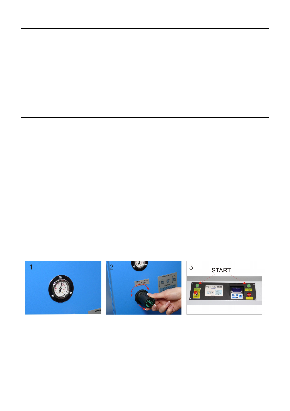
To adjust the pressure do the followin :
1. Take the pressure readin . (p oto 1)
2. To alter the pressure pull the knob to you. (p oto 2)
◦Rotatin the knob to the ri ht will increase the pressure (p oto 2)
◦Rotatin the knob to the left will decrease the pressure (p oto 2)
3. To retain the settin push the knob to the press a ain.
4. Test the pressure (p oto 3)
The pressure readin you may take at the top on the ri ht.
1,0 bar - ca. 830 k
2,0 bar - ca. 1720 k
3.0 bar - ca. 2550 k
4.0 bar - ca. 3380 k
5,0 bar - ca. 4210 k
6.0 bar - ca. 5040 k
If you alter the pressure to a settin hi her than 6 bar, a safety valve will be activated. In this case you have to reduce the pressure.
Version 17.01
10/17
Tabla de contenidos
Otros manuales de Herramientas eléctricas de Schulze

Schulze
Schulze Swing S Duo pneu Manual de usuario

Schulze
Schulze Cap Press Manual de usuario

Schulze
Schulze BluePRESSLine Mug 4 plus Manual de usuario

Schulze
Schulze AirPress4 Guía rápida

Schulze
Schulze BluePRESSLine DTG-4-S Manual de usuario

Schulze
Schulze DTG Press Manual de usuario

Schulze
Schulze Pneu Press Manual de usuario

Schulze
Schulze Air press-4 X Manual de usuario

Schulze
Schulze BluePRESSLine Mug 4 Manual de usuario

Schulze
Schulze BluePRESSLine Size 3-S Manual de usuario


