Samsung MCM-B102 Manual de usuario

Power Distribution Unit
MCM-B102
INSTALLATION
MANUAL
System Air Conditioner
EDB98-26318A(1)
MCM-B102 IM_E_26318 7/25/06 1:43 PM Page 25

Safety Precautions
◆Read this installation manual carefully before
installation and check whether the power distribution
unit is installed properly.
◆Do not attempt to install or repair the power
distribution unit by yourself.
◆Always consult an authorized service personnel for
repair.
◆When moving, consult an authorized service
personnel for disconnection and reinstallation of the
power distribution unit.
◆Ensure that the wall is strong enough to support the
weight of the power distribution unit.
◆The power distribution unit must be installed with the
rated power supply.
◆The power distribution unit must be installed
according to the national electrical rules by an
installation specialist.
◆Consult an authorized installation center on how to
dispose the power distribution unit.
WARNING
CAUTION ◆
Do not use inflammable gases near the power
distribution unit.
◆
Do not install the power distribution unit in a location
where it will come into contact with combustible
gases, machine oil, sulphide gas, etc.
◆
Avoid a location where acid/alkali solution or special
spray is used.
◆
Install the power distribution unit in a location that is
not exposed to direct sunlight and where the
temperature range is between 0°C and 39°C.
◆
Do not let water into the power distribution unit.
◆
Do not apply pressure to the cable.
The cable may break and cause fire.
◆
Do not press the buttons with a sharp object.
◆
Do not connect the power cable to the control terminal.
◆
Ensure that the power distribution unit does not affect
other electronic devices when installed in a hospital
or other particular places.
E-2
This installation manual explains how to install the power distribution unit.
See the appropriate installation manual for other optional accessories.
MCM-B102 IM_E_26318 7/25/06 1:43 PM Page 2

E-3
Contents
◆
P
OWER DISTRIBUTION UNIT PARTS
. . . . . . . . . . . . . . . 4
◆
S
YSTEM DIAGRAM
. . . . . . . . . . . . . . . . . . . . . . . . . . . 5
◆
I
NSTALLING THE POWER DISTRIBUTION UNIT
. . . . . . . . 6
◆
S
WITCH SETTING OF THE POWER
DISTRIBUTION UNIT
PCB . . . . . . . . . . . . . . . . . . . . . . 7
◆
S
ETTING THE POWER DISTRIBUTION UNIT
■ ENTERING THE SETUP MODE . . . . . . . . . . . . . . . . . . . . . . . . . . . . 8
■ SELECTING THE SET/FAN MODE . . . . . . . . . . . . . . . . . . . . . . . . 9
■ RETURNING TO THE INITIAL MODE . . . . . . . . . . . . . . . . . . . . . . . . 9
■ SELECTING THE COMMUNICATION PROTOCOL OF A DIGITAL
ELECTRIC METER . . . . . . . . . . . . . . . . . . . . . . . . . . . . . . . . . . . . 10
■ ENTERING THE INDOOR UNIT FAN POWER CONSUMPTION . . . . . . . 1
■ CHANGING THE PASSWORD . . . . . . . . . . . . . . . . . . . . . . . . . . . . 15
◆
T
EST OPERATION
. . . . . . . . . . . . . . . . . . . . . . . . . . 16
◆
T
ROUBLESHOOTING FOR COMMUNICATION ERROR
. . . 17
◆
U
SING THE POWER DISTRIBUTION UNIT
. . . . . . . . . . 18
◆
I
NDOOR UNIT FAN POWER CONSUMPTION TABLE
. . . . 19
◆
S
YSTEM SETUP MODE
. . . . . . . . . . . . . . . . . . . . . . . 1
MCM-B102 IM_E_26318 7/25/06 1:43 PM Page 3

E-4
Power distribution unit parts
A/M CLS
1234
5678
90
Ent
Mode
Room
Total
KWH
KWH
Auto/Manual search
button (For users)
Buttons for setting the
communication protocol
between the digital electric meter
and the power distribution unit
(For technicians)
Search button for
consumed electric power
of each room
(For users)
Displays the total or
individual electric
power consumption
◆
◆
◆
CC
CCAA
AAUU
UUTT
TTII
IIOO
OONN
NN
The power distribution unit must be installed by an
installation specialist.
Ensure the main power is off before installing the power
distribution unit.
All cables must be installed according to the national
wiring regulation and make sure the wires are installed
inside the wall to avoid user contact.
Power distribution unit
MCM-B102 IM_E_26318 7/25/06 1:43 PM Page 4

E-5
System diagram
Communication cable
Power supply line
➁
➃
➂
①✽
Digital electric meter(common)
①
ELB or NFB :
◆
Interceptor of air conditioners
➞
Main power breaker
➁
Power distribution unit :
◆
MCM-B102
➂
DVM air conditioners
➃
MCM-B102 IM_E_26318 7/25/06 1:43 PM Page 5

E-6
ON
1 2
Mode
RoomRoom
TotalTotal
KWHKWH
KWHKWH
SET NET
A/M CLS
1234
5678
90
Ent
Open the power distribution unit cover.
1
Connect the power cable of the power distribution unit
to the power terminal.
2
Connect the communication cable F1, F2 of the indoor and
outdoor unit to the power distribution unit terminal JP201.
3
Connect the digital electric meter communication cable
to the power distribution unit terminal JP203.
4
Reassemble the power distribution unit.
5
Installing the power distribution unit
The communication cable and the power cable
should be installed separately.
CC
CCAA
AAUU
UUTT
TTII
IIOO
OONN
NN
JP201 JP203 JP202
JP201 JP203 JP202
Indoor/Outdoor unit
communication line
Power
(220V)
JP203 JP202JP201
Digital electric meter
communication cable
MCM-B102 IM_E_26318 7/25/06 1:43 PM Page 6
E-7
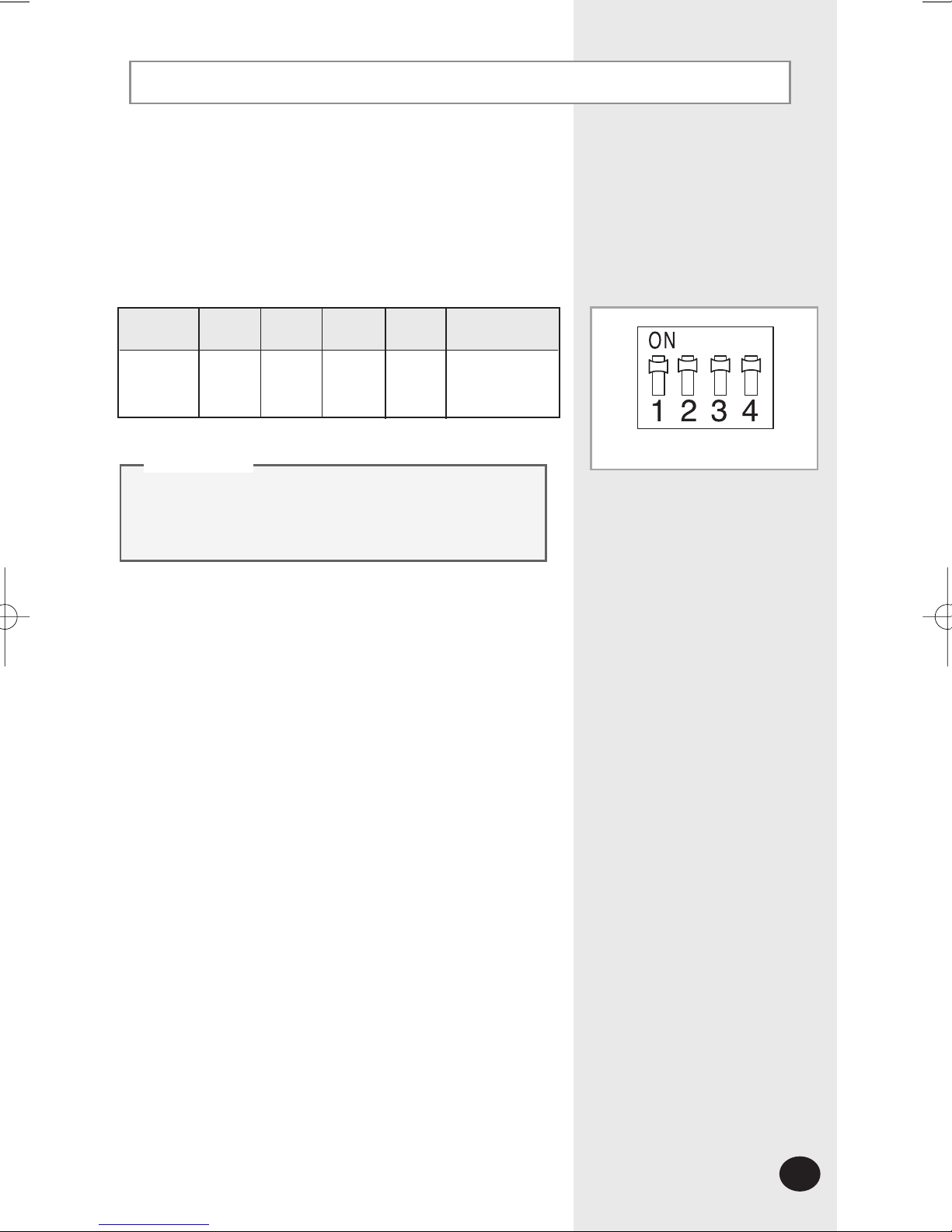
Switch setting of the power distribution unit PCB
Set the DIP switch of the power distribution unit
according to the type of digital electric meter to be
installed. Adjust the switch as shown in the table below.
If the DIP switch of the power distribution
unit PCB is not adjusted properly,
communication error may occur.
CC
CCAA
AAUU
UUTT
TTII
IIOO
OONN
NN
SW1 SW2 SW3 SW4
Switch
status
Remarks
Use RS 485
communication
ON ON OFF OFF
Factory setting of the switch
SW201
MCM-B102 IM_E_26318 7/25/06 1:43 PM Page 7

E-8
Setting the power distribution unit
A/M CLS
1234
5678
90
Ent
Mode
Room
Total
KWH
KWH
Mode
Room
Total
KWH
KWH
Enter the setup mode to set the system environment of the
power distribution unit.
Press the , , , buttons on the
key-pad of the power distribution unit in sequence.
1
Press the button again when appears on
the display.
2
Press the button after entering the password
when appears on the display.
◆
The default password is '0000000'.
3
If there are no key inputs for 3 seconds when
appears on the display, the display
returns to the initial mode.
CC
CCAA
AAUU
UUTT
TTII
IIOO
OONN
NN
Entering the setup mode
9
0
Ent
Ent
Ent
MCM-B102 IM_E_26318 7/25/06 1:43 PM Page 8

E-9
Press the or button to select the mode when
the setup screen appears.
◆
Each time you press the or button, you can select
the SET/FAN mode.
◆
The SET mode is selected by default.
1
You can enter each mode by pressing the button.
2
Selecting the SET/FAN mode
Ent
Mode
Room
Total
KWH
KWH
SET
Mode
Room
Total
KWH
KWH
FAN
When selecting the SET mode
▼
When selecting the FAN mode
Press the or button until
appears on the
display in the setup mode and press the button.
◆ The mode changes from the setup mode to the initial mode.
2
Press the or button until appears on the
display in the SET/FAN mode and press the button.
◆
The mode changes from the SET / FAN mode to the setup
mode.
1
1
2
Ent
Ent
Returning to the initial mode
Mode
Room
Total
KWH
KWH
SET
Mode
Room
Total
KWH
KWH
MCM-B102 IM_E_26318 7/25/06 1:43 PM Page 9

E-10
Setting the power distribution unit (Continued)
Press the button.
◆ The existing setting of the communication protocol is deleted
and you can enter a new setting.
Select the SET mode and press the button after
entering the setup mode.
1
Press the button twice when appears on the
display.
◆ The default communication protocol setting is '1'.
2
Selecting the communication protocol of
the digital electric meter
Ent
Ent
2
3
Mode
Room
Total
KWH
KWH
SET
Mode
Room
Total
KWH
KWH
SET
Press the button after entering the desired setting of
the communication protocol.
4
Ent
Button(Setting) 123
Communication
protocol of a
digital electric
meter
Omni
RS 485
Korea
Micronics
RS 485
LS
Industrial
RS 485
7
Hansuk
Tech
RS 485
MCM-B102 IM_E_26318 7/25/06 1:43 PM Page 10
Tabla de contenidos


