SAFEMATIC 361034B Manual de instrucciones

MULTILUBE
INSTALLATION AND MAINTENANCE
HINS4AEN.doc 24.08.2006 Rev. 4A
MULTILUBE –SYSTEM INSTALLATION AND MAINTENANCE
TABLE OF CONTENTS
1 PUMPING UNIT INSTALLATION......................................................................................................................1
1.1 Installing the supporting blocks and the pumping unit................................................................................1
1.2 Installing the main line on the pumping unit................................................................................................3
1.3 Installing the safety switch..........................................................................................................................4
2 EXTERNAL CONNECTIONS............................................................................................................................5
2.1 Removing the cover....................................................................................................................................5
2.2 Installing the cables and electrical connections..........................................................................................7
3 PUMPING UNIT MAINTENANCE.....................................................................................................................9
3.1 Removing the shell......................................................................................................................................9
3.2 Fastening of the shell................................................................................................................................10
4 REPLACING THE PUMP ELEMENT..............................................................................................................12
5 REPLACING THE LINE VALVE......................................................................................................................14
6 FILLING THE LUBRICANT RESERVOIR OF THE PUMPING UNIT .............................................................16
7 REMOVING AIR FROM THE PUMPING UNIT...............................................................................................17
8 CONTACT INFORMATION.............................................................................................................................17
9 INSTALLING SIM-CARD TO GSM-MODEM (OPTION).................................................................................18
MULTILUBE
INSTALLATION AND MAINTENANCE
HINS4AEN.doc 24.08.2006 Rev. 4A
1 (18)
MULTILUBE –SYSTEM INSTALLATION AND MAINTENANCE
1 PUMPING UNIT INSTALLATION
1.1 Installing the supporting blocks and the pumping unit
Note Free space is required below the pumping unit for maintenance procedures.
See dimensional drawings 361034B and 361035B.
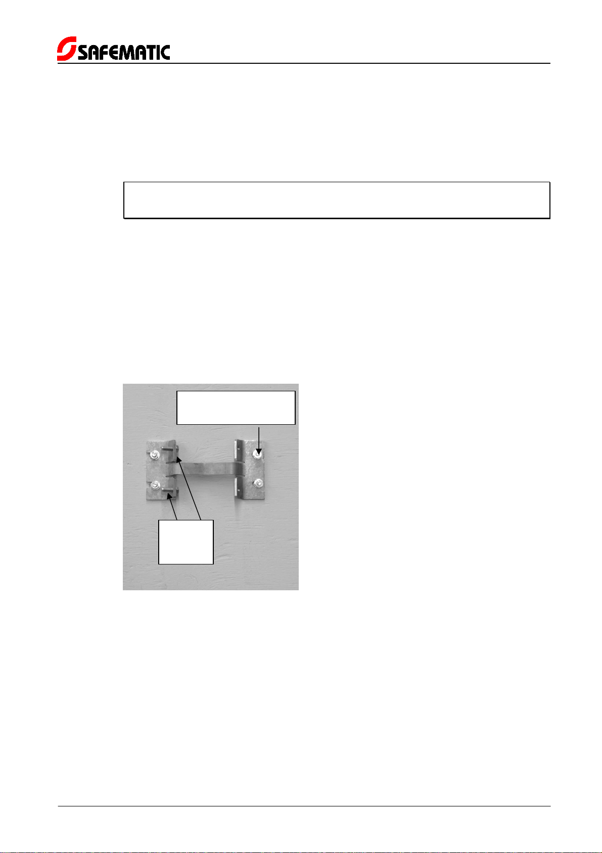
Installing the supporting block of pumping unit models MLP-4-X-XX-XX-XX:
1. Determine the location of the supporting block with the help of the dimensional drawings.
2. Install the supporting block in its place with cotter bolts M8x75 or with hexagonal screws
M8 (4 pcs) (Figure 1).
3. Install 2 pcs M8x25 hexagonal screws on the other side of the block.
4. Lift the pumping unit on the wall on the M8 hexagonal screws.
5. Install 2 pcs M8 hexagonal screws on the other side of the block.
6. Fasten the pumping unit on the supporting block by tightening the M8 hexagonal screws (4
pcs).
Figure 1. Supporting block installed on a wall
Hex.
screw
M8x25
Cotter bolt M8x75 or
hex. screw M8 (4 pcs)
MULTILUBE
INSTALLATION AND MAINTENANCE
HINS4AEN.doc 24.08.2006 Rev. 4A
2 (18)
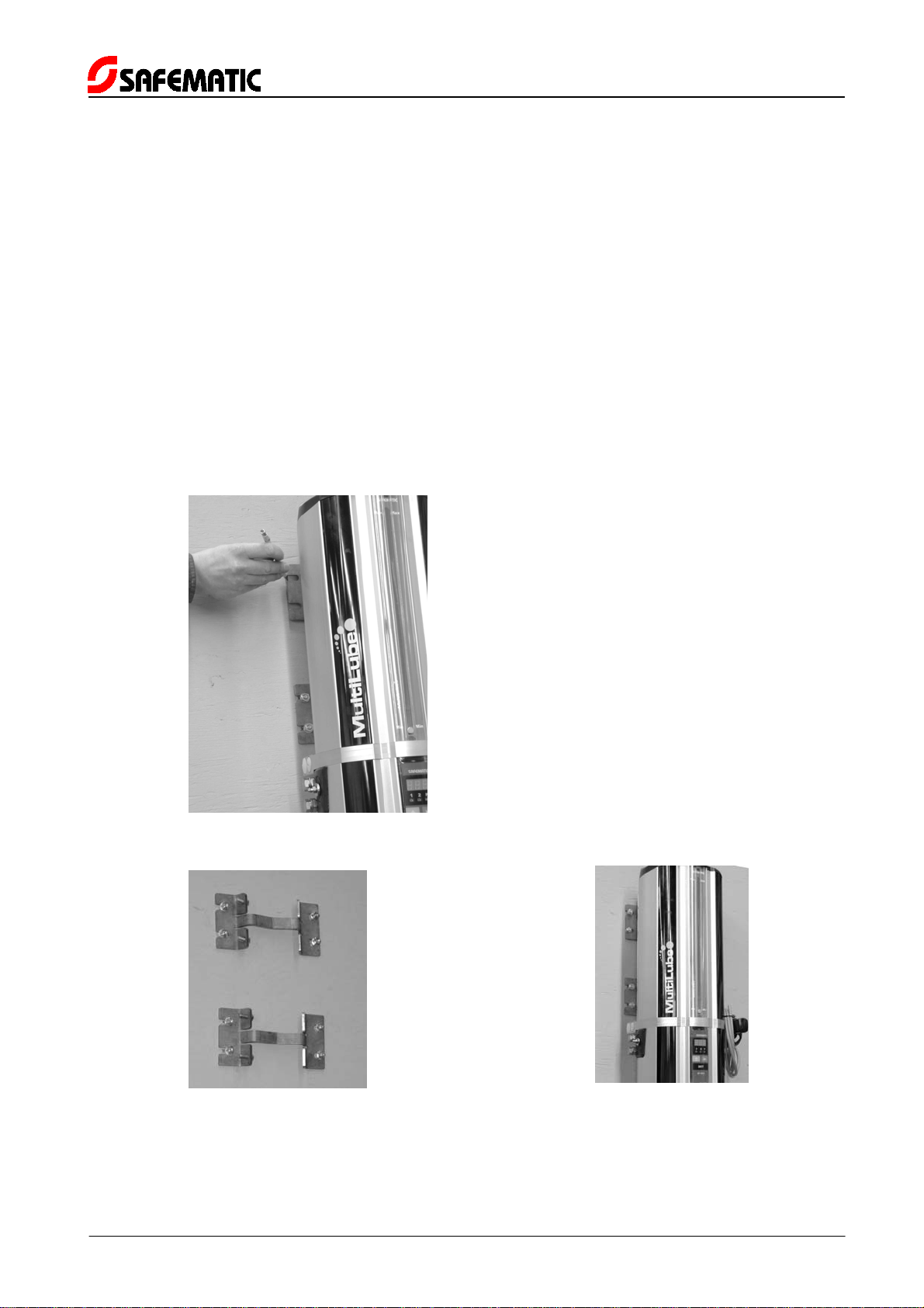
Pumping unit models MLP-10-X-XX-XX-XX include 2 pcs supporting blocks:
1. Determine the location of the supporting block with the help of the dimensional drawings.
2. Install the first supporting block in its place with cotter bolts M8x75 or with hexagonal
screws M8 (4 pcs) (Figure 1).
3. Install 2 pcs M8x25 hexagonal screws on the other side of the block.
4. Install the other supporting block on the pumping unit with M8 hexagonal screws.
5. Lift the pumping unit on the M8 hexagonal screws of the supporting block which is already
installed on the wall.
6. Mark the place of the other supporting block (Figure 2).
7. Lift the pumping unit down.
8. Uninstall the block from the pumping unit and install it on the wall with cotter bolts M8x75
or with hexagonal screws M8 (4 pcs) (Figure 3).
9. Lift the pumping unit on the wall on the M8 hexagonal screws.
10. Fasten the pumping unit on the supporting blocks by tightening the M8 hexagonal screws
(8 pcs).
Figure 2. Marking the place of the other supporting block
Figure 3. Supporting blocks
installed on a wall
Figure 4. Pumping unit installed
on the supporting
blocks
MULTILUBE
INSTALLATION AND MAINTENANCE
HINS4AEN.doc 24.08.2006 Rev. 4A
3 (18)
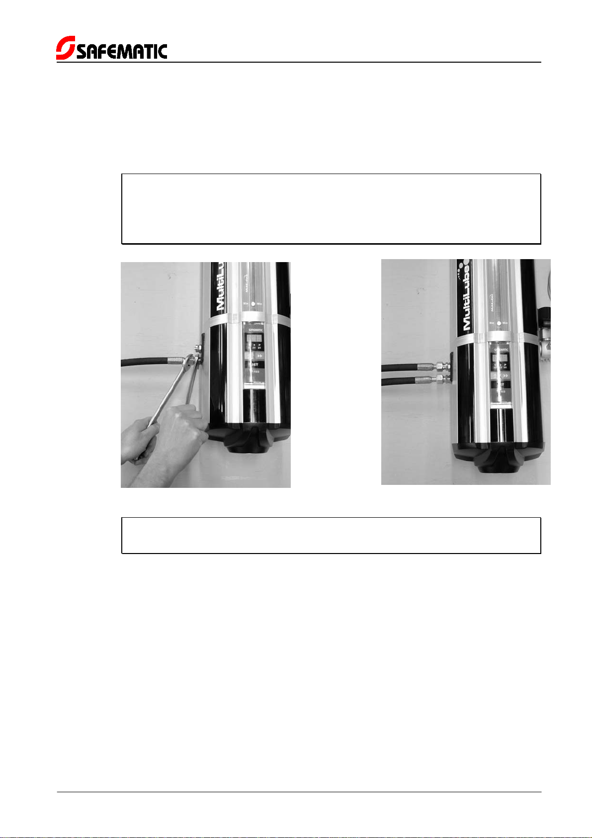
1.2 Installing the main line on the pumping unit
In single-line models the main line is installed in the lower pressure connection (Figure 5). The
upper pressure connection remains plugged.
In dual-line models main lines are installed in both pressure connections (Figure 6).
Note Hose assembly is recommended in installation of main lines (e.g. Safematic
code 12653750). The following components are required between the
pumping unit and the hose assembly: male connector 12 L R1/4 ZN (e.g.
Safematic code 12805220) and gasket Usit 217-04 (e.g. Safematic code
11682550).
Figure 5. Single-line model
Figure 6. Dual-line model
Caution Support the connector body while tightening the connector nut to prevent
damage to the threads of the pumping unit (Figure 5).

MULTILUBE
INSTALLATION AND MAINTENANCE
HINS4AEN.doc 24.08.2006 Rev. 4A
4 (18)
1.3 Installing the safety switch
Warning Pumping unit models with power input 230 V or 115 V have to be equipped
with a safety switch (e.g. Safematic code 10543062).
Installing the safety switch:
1. Install the safety switch next to the pumping unit (Figure 7).
2. Feed cable into the safety switch as shown in Figure 8.
3. Electrical connections are made according to a separate electrical drawing which is
delivered with the pumping unit.
Warning Electrical connections may only be made by a qualified electrician.
Figure 7. Safety switch next to
the pumping unit
Figure 8. Cable inside the
safety switch
MULTILUBE
INSTALLATION AND MAINTENANCE
HINS4AEN.doc 24.08.2006 Rev. 4A
5 (18)
2 EXTERNAL CONNECTIONS
2.1 Removing the cover
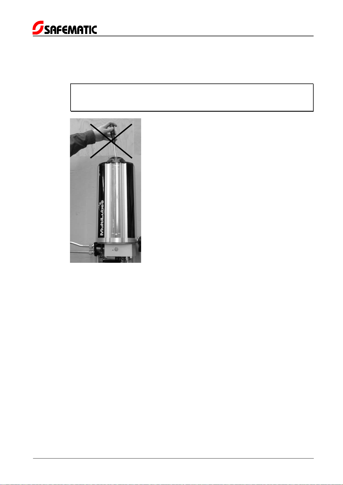
Warning The reservoir MAY NOT BE OPENED when the pumping unit is installed
and operational (Figure 9). The risk is that the pumping unit may fall down
and damage.
Figure 9. The reservoir of the pumping unit may not be opened

MULTILUBE
INSTALLATION AND MAINTENANCE
HINS4AEN.doc 24.08.2006 Rev. 4A
6 (18)
Maintenance of the pumping unit and external electrical connections:
1. Open the screw (Figure 10).
2. Remove the cover plate and gasket (Figure 11).
3. Open the nut (Figure 12).
4. Remove the nut and the star washer (Figure 13).
5. Remove the cover (Figure 14).
Figure 10. Open the screw
Figure 11. Remove the cover
plate and gasket
Figure 12. Open the nut
Figure 13. Remove the nut and
the star washer
Figure 14. Remove the cover

MULTILUBE
INSTALLATION AND MAINTENANCE
HINS4AEN.doc 24.08.2006 Rev. 4A
7 (18)
2.2 Installing the cables and electrical connections
Warning Electrical connections to the terminal blocks may only be made by a
qualified electrician.
1. Remove the cover, see paragraph 2.1 .
2. Remove the protective plug of the cable gland (Figure 15).
3. Bend the cable end a little curved (Figure 16). This makes the feeding of the cable easier.
4. Push the cable through the cable gland to the terminal block (Figures 17 and 18).
5. Put an appropriate screwdriver in the upper opening of the terminal block.
Caution Do not twist the screwdriver, only put it in the opening.
6. The cable to be connected is put in the lower opening. The cable is locked when the
screwdriver is detached from the upper opening (Figure 19).
Figure 15. Removing the
protective plug
Figure 16. Feeding the cable
Figure 17. Feeding the cable
through the cable
gland
Figure 18. Cable at the terminal
block

MULTILUBE
INSTALLATION AND MAINTENANCE
HINS4AEN.doc 24.08.2006 Rev. 4A
8 (18)
Figure 19. Connecting the wires to the terminal block

MULTILUBE
INSTALLATION AND MAINTENANCE
HINS4AEN.doc 24.08.2006 Rev. 4A
9 (18)
3 PUMPING UNIT MAINTENANCE
3.1 Removing the shell
1. Remove the cover, see paragraph 2.1 .
2. Disconnect the protective grounding wire (Figures 20 and 21).
3. Remove the shell by gently pulling downwards (Figure 22).
4. Disconnect the cable of user interface from the circuit board (Figures 23 and 24).
Figure 20. Detach the fastening
of the protective
grounding wire
Figure 21. Disconnect the
protective grounding
wire
Figure 22. Removing the shell
Figure 23. Cable of user
interface IF-103
Figure 24. Disconnecting the
cable of user interface
IF-103
Figure 25. Pumping unit without
the shell for
maintenance
Este manual sirve para los siguientes modelos
1
Tabla de contenidos
Otros manuales de Bomba de agua de SAFEMATIC

Manuales populares de Bomba de agua de otras marcas


Sykes AmeriPumps
Sykes AmeriPumps GP100M Guía de solución de problemas

DUROMAX
DUROMAX XP WX Series Manual de usuario

BRINKMANN PUMPS
BRINKMANN PUMPS SBF550 Manual de usuario

Franklin Electric
Franklin Electric IPS Manual de usuario

Xylem
Xylem e-1532 Series Manual de usuario

Milton Roy
Milton Roy PRIMEROYAL Manual de usuario