RUBETEK HD-1 Manual de usuario

MANUAL
ADDRESSABLE HEAT DETECTOR
HD-1 «RUBETEK»
Complies with:
EN 54-5
Hardware version: IP101-102M rev.4
Software version: 2022-10-1
Document version: 2022-10-1

2
Table of contents
Introduction..........................................................................................................................................3
1. Description and operation...........................................................................................................4
1.1. Function......................................................................................................................................4
1.2. Technical data.............................................................................................................................4
1.3. Apprearance of the detector........................................................................................................5
1.4. Internal design of the detector....................................................................................................5
1.5. Complete set...............................................................................................................................6
2. Intended use................................................................................................................................6
2.1. Preparation for use......................................................................................................................6
2.2. Detector location.........................................................................................................................6
2.3. Installation..................................................................................................................................7
2.4. Detector connection to CP..........................................................................................................8
2.6. Detector deactivation................................................................................................................12
2.7. СP bypass mode........................................................................................................................13
2.8. «Fire 2» confirmation alarm signal configuration....................................................................13
3. Maintenance..............................................................................................................................14
3.1. Safety precautions.....................................................................................................................14
3.2. Functional test...........................................................................................................................14
4. Storage......................................................................................................................................15
5. Transportation...........................................................................................................................15
6. Disposal....................................................................................................................................16
7. Manufacturer’s warranty ..........................................................................................................16
8. Claims.......................................................................................................................................16
9. Certification..............................................................................................................................16
10. Manufacturer ............................................................................................................................16
11. Supplier...........................................................................Ошибка! Закладка не определена.

3
Introduction
This Manual is intended to describe the operating principle, configuration, installation and
operation of the addressable heat detector HD-1 «RUBETEK» (hereinafter detector).
Detector operates under control of the addressable fire alarm control panel as part of the
«RUBETEK» fire alarm system.
You must read the instructions in the Manual before linking, configuring, operating or
maintaining the detector.
Installation and operation of the detector must be carried out by technical personnel after
reading this Manual.
List of abbreviations used:
−Base - detector base DB-1 «RUBETEK»;
−CP - addressable fire alarm control panel;
−CW - commissioning works;
−DEVs - alarm and notification devices;
−FA - fire alarm;
−Fire 1 - First alarm state;
−Fire 2 - Сonfirmation alarm signal;
−HD, detector - addressable heat detector HD-1 «RUBETEK»;
−PLC - power line communication;
−SCI - short circuit isolator module.

4
1. Description and operation
1.1. Function
Addressable heat detector HD-1 «RUBETEK» is designed to protect objects from fires by
controlling the rate of temperature increase, exceeding the threshold value and issuing notifications
«Fire», «Attention» or «Normal» to addressable fire alarm control panel (CP) via wired
communication link.
The detector operates as part of the Rubetek automatic fire alarm system, controlled by the
addressable fire alarm control panel CP-1 (hereinafter referred to as CP).
Detector functional capabilities:
•It has two methods for determining fires - by maximum temperature and by
temperature increase rate;
•generation of «Fire» and «Fault» alarms;
•automatic device detection in the system;
•testing of the detector from the CP menu;
•monitoring of the functionality;
•status light indication;
•PLC voltage measurement at the installation site;
•setting in the service mode, without interruption of the link and configuration;
•easy circular attachment to the base;
•protective housing;
•modern design.
1.2. Technical data
Table 1 - The main parameters of the detector
Parameter
Value
Link interface
PLC
Voltage supply
via PLC
Current consumption, mA
–max 0,17 in Standby mode
–max 0,2 in «Fire» mode
Detector activation temperature, °С
from + 54 to + 65
Operation temperature range, °С
from - 25 to + 55
Relative air humidity
Up to 93% at +40°С
Detector grade
A1R
Dimensions, mm
Ø 92 × 42
The degree of protection for the case
IP20
Weight, g, max
75 ± 5%
Average lifetime, years
10

5
Average time between failures, h
60000
1.3. Apprearance of the detector
1 - Case cover
2 - LED indicator
3 - «Test» button
4 - Device case
5 - Base
Figure 1 - Appearance of the detector (front view)
1 - Detector case
2 - Detector contacts
3 - Base
4 - Terminals to connect to PLC
5 - Mounting holes
Figure 2 - Appearance of the detector (back view)
1.4. Internal design of the detector
1 - «Tamper» sensor
2 –Terminals to connect to PLC
Figure 3 –Internal design of the detector

6
1.5. Complete set
Table 2 - Complete set of the detector
Item
Quantity, ea
Remarks
Addressable heat detector HD-1 «RUBETEK»
1
Detector base DB-1 «RUBETEK»
1
Installed on
detector
Protective housing
1
Installed on
detector
Mounting kit
1
Datasheet
1
Multiple package
1*
* Per shipment.
2. Intended use
2.1. Preparation for use
ATTENTION! If the detector was in conditions of negative temperature, keep it at least
4 hours at room temperature (25 ± 10 ºС) to prevent moisture condensation.
Open the package, make sure that the completeness of the detector corresponds to table 2.
Conduct an external visual inspection, make sure that there are no visible mechanical damages
(chips, cracks, dents) and traces of moisture.
Prepare CP for operation (you may find the complete connection algorithm in the User Manual
for CP).
2.2. Detector location
Do not install a detector:
●outdoors, in places where there is a possibility of water getting on the detector case;
●in a room with a high content of dust, suspensions of building materials in the air, vapors and
aerosols that cause corrosion;
●in places with high air currents (for example, near fans, radiators and ventilation ducts);
●near high-frequency communications, power cables, routes.
Basic requirements for the organization of PLC and power lines:
●cable lines must be made with using fire-resistant cables with copper cores, flame
retardant for group laying, low-smoke fire-resistant (LSFR) or halogen-free (HFFR);
●● nominal wire cross-section from 0,75 mm² to 1,5 mm².

7
2.3. Installation
ATTENTION! All PLC lines are connected prior to equipment installation.
Open the case of the detector. To do this, turn
the base of the detector counterclockwise, and
with a little effort pull the base of the detector.
Attach the device base to the selected
installation location and mark the mounting
holes with a pencil.
Drill 2 holes.
Terminate the PLC line at the base mounting
location, ensuring the possibility of connecting
the PLC to the detector terminals.
Fasten the detector base to the surface of the
PLC line using the mounting kit from the
accessory kit.
1 - Base
2 - Screw
3 - Dowel
Connect the detector to PLC line in any
sequence of input terminals.
ATTENTION! Install the detector on
the base only after switching the CP to
the mode of searching for available
devices (see. paragraph 2.4).

8
- Install the detector on the base, aligning the
projections of the case with the recesses on the
base. Sink the case in the base until it stops.
- Rotate the detector clockwise.
2.4. Detector connection to CP
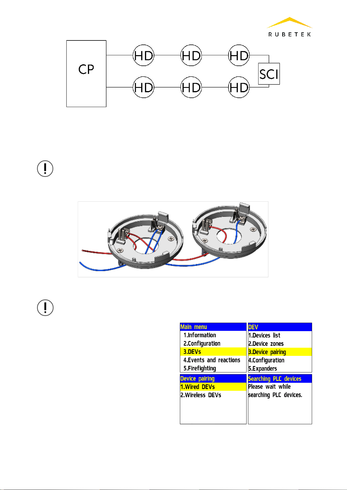
The connection can be carried out by the «tree» or «ring» topology. When connected by the
«tree» topology within one protected zone, the detectors are connected sequentially within the
«branch», branching is carried out thanks to the «connector box» (see Figure 4). When connecting by
the «tree» topology within several protected zones and by the «ring» topology, an SCI-1 short circuit
isolator module connection is required (see Figure 5 and Figure 6).
Figure 4 - Connection diagram by the «tree» topology for one alarm zone
Figure 5 - Connection diagram by the «tree» topology for several alarm zone
9
Figure 6 - Connection diagram by the «ring» topology
The detector operates under the CP control, all detector configurations are made through the
device software.
When connecting wired devices, it is necessary to take into account the maximum length of
the PLC from the CP to the end device, which should not exceed 1200 meters.
ATTENTION! Binding of wired devices is performed one by one, i.e. it is necessary to install
each detector on the base in turn, then bind this device to the CP, and only after that proceed
to installing the detector on the base and its binding.
Figure 7 - Detectors connection diagram
ATTENTION! Before pairing the devices, all PLC lines and device bases must be installed.
In the Main menu of CP select 3.DEVs and
press Ок
- select 3.Device pairing in the submenu. Press
Ок.
- select 2.Wired DEVs in the submenu. Press
Ок.
CP will go to automatic devices search.
After the search is completed, the CP will
display a list of found devices.
Select the required device. Press OK. The name
of the device is followed by its serial number.
The CP automatically pairs a new wired device
to the first free slot.
The device configuration menu will open.
After making all the configurations, press OK.

10
Device configuration
If you are making configurations for a
previously paired and configured device, you
must:
- select item 3.DEV and press OK
- select submenu 1.Devices list. Press OK.
- select submenu 2. Wired DEV. Press OK.
- select the desired slot. Press OK.
If configurations are made during pairing, the
configuration menu will be available
immediately.
The following options are available in the
list that opens.
●Name –device name;
●Zone - will allow you to combine
devices of one fire zone. There are 32
protected zones on the CP;
●Device type* - determined
automatically;
●Status* - current status of the detector
(normal, Fire 1, Fire 2, link fault);
●Bypass mode - bypass mode on/off;
●Temperature* - value of the current
temperature of the thermistor;
●Heating rate - rate of temperature
change over time;
●Link* - time since last link;
●PLC Line* - PLC line voltage;
●Serial number* - device serial number;
●Firmware version* - device firmware
version;
Tabla de contenidos
Otros manuales de Sensor de seguridad de RUBETEK


