ADAM 2 Introduction | en 7
Bosch Security Systems, LLC Technical Manual 2020-11 | 01 | F.01U.388.223
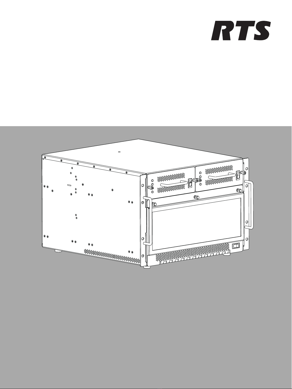
2 Introduction
The RTS family of Digital Intercom Matrices is the most extensive, widely used, scalable and
backwards compatible line of intercoms in the world today. The high-end ADAM 2 Matrix
supports 8 to 880 users per system; 512 ports possible in just a seven RU (Rack Units) frame.
Utilizing a patented TDM (Time Division Multiplex) technique, the ADAM 2 grows linearly as
users are added. The system comes standard with redundant universal power supplies
(100-240 VAC), and supports redundant controllers, allowing for automatic change-over in the
event of failure.
ADAM 2 is available with a wide variety of Interface cards in the industry, including the
MADI-16, OMI, AIO-16A, and RVON + interfaces. It also has the wide variety of cabling options,
including RJ11, RJ45, DB9, jack fields, and many others.
With its second generation controller card, Ethernet connectivity is achieved between the
ADAM 2 Intercom and AZedit. ADAM 2 can support 32 simultaneous AZedit sessions.
Features
– Supports all standards including VoIP, OMNEO, DANTE, Analog, SMPTE 2110, MADI, and
more depending on cards populated in the frame.
– The new ADAM 2 is designed with quieter fans, universal power supplies that operate in
all countries and is compatible with ALL current and legacy RTS keypanels and
accessories. It comes standard with multi-level IFB, ISO, Party-Lines, Groups, and GPIs. It
supports from 8 to 880 users.
– Supports real-time monitoring online and offline configuration and RTS UPL (User
Programmable Language) for custom system configurations via pull-down menus.
– In addition to digital and VoIP cards, the analog dual-purpose ports support both
keypanel and 4-wire audio.
– Integrated support for RTS Intelligent Trunking of 255 matrices (ADAM, ADAM-CS, ADAM-
M, ADAM 2, Cronus, Zeus III, and ODIN).
Unpacking the components
– Unpack the contents of the shipping crates and carefully inspect for damage.
– Notify the freight carrier immediately if any damage is noted.
– Check off all items as noted in the packing lists.
Caution!
Use caution when lifting the system components.
A fully loaded ADAM 2 card frame weighs approximately 75 lbs (34 kg).