Rontan Maximum Super Takedown Manual

Maximum Super Takedown
Installation, Operation & Programming Instructions
www.rontan.com Rev. 0.3 Page 1
The Maximum Super Takedown Lightbar:
Designed for multiple vehicle applications.
Available in 5 and 6 dome models
Designed and intended to function as an emergency warning light, with super
takedown, alley and directional stick options.
Assembled on SMD technology.
Intended for roof mount application.
Operated independently or in conjunction with Rontan light controllers (ICM40®,
DSC40®, Intelligent Siren –IS3000, etc.).
Stores all flash patterns in the light assembly intelligence.
Plug and Play operability and modular design of the light heads facilitate
installation, quick color changes, and field upgradeability.
Engineered with Rontan two-wire technology for ease of installation and quick
programming.
6 takedown modules in the 45” and 8 takedown modules in the 54” lightbars.
Note:
All Rontan North America products are SAE compliant and meet Calif. Title 13
standards.

Maximum Super Takedown
Installation, Operation & Programming Instructions
www.rontan.com Rev. 0.3 Page 2
Safety Message
WARNING
Before beginning installation of your lightbar, it is important to read these
instructions for the safe, correct installation and operation of this product.
Proper installation of this product requires the installer have good understanding of
automotive electrical systems and procedures.
Light system controls must be located so that the vehicle and controls can be
operated safely under all driving conditions.
DO NOT route any wires in the deployment path of your airbag. Refer to the vehicle
owner’s manual for the airbag deployment area.
Before drilling into a vehicle structure, verify carefully if both sides of the surface are
clear of anything that could get damaged. Install grommets into all wire passage
holes.
DO NOT drill any holes in the lightbar.
A lightbar system is a high current device. In order for it to function properly, a good
electrical ground connection must be made.
This lightbar is intended for use by authorized personnel only. The users have the
responsibility to ensure they operate the emergency warning devices in compliance
with the applicable laws and regulations.
File these instructions in a safe place and refer to them when performing
maintenance and/or reinstallation of this product.
Failure to follow all safety precautions and instructions may result in damage
to the product and vehicle or serious injury to individuals!

Maximum Super Takedown
Installation, Operation & Programming Instructions
www.rontan.com Rev. 0.3 Page 3
Introduction
Super Takedown is a new feature for the best-selling Rontan Maximum Wide-E-Tech
Lightbar.
This new feature has been added to this lightbar architecture through the customizable
capability that our new Rontan products offer.
It consists of white LEDs spread across the front modules, without sacrificing the
regular lightbar colors. On the rear the same concept is applied to the Amber LEDs for
the Directional Stick function.
1. Specification
Voltage: 12,8 V +/- 15%
Electric Current
NOMINAL SIZE
Maximum current (A)
FUSE AMPERAGE
45”
14
30A
54”
14
30 A
Super Takedown Light Heads:
All the front light heads will be Super Takedown modules for both sizes of lightbar.
The 45” will have 6 Super TD light heads and the 54” will have 8 Super TD light heads.
NOTE: If extra wire is needed, make certain to use larger gauge wire than supplied
with the lightbar.
Dimensions

Maximum Super Takedown
Installation, Operation & Programming Instructions
www.rontan.com Rev. 0.3 Page 4
Nominal Size
Dimension
A (in)
6 domes
45
7 domes
54
2. Installation
2.1. Mounting the hardware
Follow the steps below for proper hardware installation:
The Migfoot*
A. Insert the mounting bolts into the groove on the lightbar.
B. Place the Migfoot on the mounting bolts as shown and loosely tighten the nuts using
a 10mm wrench. *Used for the 45 inch lightbar.
C. Measure the distance of each corner from the vehicle roof. Use the formula below to
calculate the distance between the center of the lightbar and the inner edge of the
migfoot.
D (in) = roof [width/2] –13.5
Examples of distance (D):
Dodge Charger: D=12¼ inches
Ford Crown Victoria: D=12 inches
Chevy Impala: D= 12 inches

Maximum Super Takedown
Installation, Operation & Programming Instructions
www.rontan.com Rev. 0.3 Page 5
D. Tighten nuts snugly. (50 in-lb).
E. If necessary, use the supplied wedge shaped rubber foot pad in both feet to adjust
the angle of the lightbar if it is not level with the roof.
F. Loosely installing the roof mounting brackets with the long threaded bolts can be
performed at this point or this task can be performed once the lightbar is
appropriately positioned on the vehicle roof. Please note: Installation at this point
will mean that these metal pieces will be hanging loosely when the lightbar is
positioned over the vehicle roof dramatically increasing the chances for damaging
the vehicle surfaces during installation. Extreme care must be taken on your behalf
to avoid vehicular damage.

Maximum Super Takedown
Installation, Operation & Programming Instructions
www.rontan.com Rev. 0.3 Page 6
G. If not previously completed, place the long threaded bolts through the large hole in
the roof brackets as shown. Thread the bolt into the cylinder nut previously installed.
Make sure that the bolt crossed the cylinder nut all the way though. A flat tipped
screwdriver may be needed to properly align the cylinder nut.
H. Loosely tighten the long threaded bolts to pull the brackets to the roof lip. Drill 7/64th
inch pilot holes using the middle and outer 2 bracket holes as guides. Apply sealant
(RTV) to the drilled holes. Fasten the brackets to the roof with the six Philips head
sheet metal screws provided (3 per side). Once the brackets are secure, torque the
long threaded bolt to 30 in-lb.
Note: When using the supplied rubber grommet, drill a 3/4 inch hole in the roof for
routing the wiring for installation completion.

Maximum Super Takedown
Installation, Operation & Programming Instructions
www.rontan.com Rev. 0.3 Page 7
2.2. The Durusfoot*
Mounting the Durusfoot
Turn the lightbar upside down, and rest it on a soft, non-scratch surface. Place the
durusfoot on four of the included bolts and tighten the nuts, making sure the distance
from the edge of each durusfoot is equally spaced (about 5 inches) from the edge of the
lightbar. Insert 4 shock absorption bolts into each durusfoot. Hand-tighten each shock
absorption bolt as much as possible. Turn the lightbar over. Position the lightbar on the
roof of the car, being careful to not scratch the finish of the car. Measure each side to
make certain the lightbar is in the desired location. Mark the location of each shock
absorption bolt on the roof, remove the lightbar and replace on the soft surface. Drill the
holes being careful to not drill into any wires or damage the upholstery. Put RTV
sealant around the holes in the roof to seal against the infiltration of water. Place the
lightbar back on the roof of the vehicle placing the shock absorption bolts through the
drilled holes, and install the flat washers and M-8 nylon insert lock nuts tighten to 50 in.
lbs. *The Durusfoot is used for the 63 inch lightbar

Maximum Super Takedown
Installation, Operation & Programming Instructions
www.rontan.com Rev. 0.3 Page 8
Note: When using the supplied rubber grommet, drill a 3/4 inch hole in the roof
for routing the wiring for installation completion.
2.3. Routing the lightbar cable
Route the light cable into the wiring shield and towards the firewall to minimize interior
intrusion and to optimize wiring. Make sure you do not pinch or crush any wires when
running them through the wire shield.
The light cable has two power wires (RED and BLACK connect directly to the
positive and negative battery terminals) and three control wires
(GREEN, YELLOW and ORANGE). Note: Shield wire is to be cut.
The following is general information to aid you in the installation of the lightbar:
A) Install a fuse block on the end of the RED wire in the power cable. Use 30A fuse.
B) Remove the fuse from the fuse block before connecting the wire to the battery.
Place the fuse back in the fuse block at the end of installation.
C) Connect the RED wire to the POSITIVE terminal of the battery.
D) Connect the BLACK wire to the NEGATIVE terminal of the battery.
E) Route the control wires towards the controller or switch control panel.
F) Connect the three control wires to the controller or switch control panel.
G) Reinstall the fuse in the block.
There are different connections between the lightbar and the controller or switch control
panel. The controller can be controlled and programmed in analog or digital mode.

Maximum Super Takedown
Installation, Operation & Programming Instructions
www.rontan.com Rev. 0.3 Page 9
Electrical diagram 1
Note:
Refer to the next section for information about operational and programming
instructions.
3. Describing the lightbar functions
This lightbar provides selectable multiple flash patterns that can be used in all
functions: MODE 1-4, AUX 1-4 and EM 1-2. It is possible to have up to 8 steady
burning lights active at one time (takedowns).
Below is a brief description of each control function:
SLIDE SWITCH MODE 1-4 provides four modes of preprogrammed flash patterns via
slide control switch as described below:
Mode 1 –Alternative corner light heads will be activated. The flashing takedown
and alley functions will NOT be activated automatically.
Mode 2 –Most of the light heads will be activated. The flashing takedown and
alley functions will NOT be activated automatically.
Mode 3 –All light heads will be activated for an intense warning effect. In mode
3, the flashing takedown and alley functions will be activated automatically.
Mode 4 (additional) - All light heads will be activated for an intense warning
effect. In mode 4, the flashing takedown and alley functions will be activated
automatically.

Maximum Super Takedown
Installation, Operation & Programming Instructions
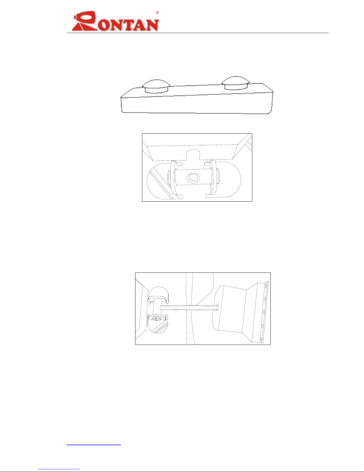
www.rontan.com Rev. 0.3 Page 10
AUX1 to AUX4: Several alternative preprogrammed flash patterns will be activated.
ALLEY-L: LEFT side lights available in LED.
ALLEY-R: RIGHT side lights available in LED.
TAKEDOWN: FRONT lights available in LED.
Steady Burn (SB): Up to 8 LED light heads will be activated simultaneously.
CRUISE: Some corner light heads will be activated in low power.
Left Directional Stick (DS-L): The REAR light heads (usually amber lights) will be
activated and produce a left arrow flashing pattern, instructing traffic to move LEFT.
Right Directional Stick (DS-R): The REAR light heads (usually amber lights) will be
activated and produce a right arrow flashing pattern, instructing traffic to move RIGHT.
Center Directional Stick (DS-C): The REAR light heads (usually amber lights) will be
activated and produce a center arrow flashing pattern, instructing traffic to move to
either side of the vehicle.
HAZARD: Hazard lights (usually amber lights) will be activated in the directional stick
function in order to alert other drivers to a problem.
EMERGENCY 1 (SUPER TAKE DOWN-STEADY): When this function is activated, all
front, white light heads will be activated in a continuous, steady burn mode.
EMERGENCY 2 (SUPER TAKE DOWN-FLASH): When this function is activated, all
front, white light heads will be activated in flashing mode (Quad Strobe).
DS1-L to DS8-R: Each input will activate each individual light head (usually amber
lights) for directional signal purposes.
CUT FRONT: Turn the front light heads OFF.
CUT REAR: Turn the rear light heads OFF.
DIMMER: The low power setting of the lightbar will be activated to decrease the
brightness of LED light heads.
Tabla de contenidos
Otros manuales de Equipo de iluminación de Rontan
Manuales populares de Equipo de iluminación de otras marcas

Qazqa
Qazqa Suplux SL 3 Black 103062 Manual de usuario

Commercial Electric
Commercial Electric 54568141 Manual de usuario

CREE LIGHTING
CREE LIGHTING 304 Series Manual de usuario

Goobay
Goobay 49867 Manual de usuario

ECOMAN ITALIA
ECOMAN ITALIA LED T8 Manual de usuario

Alkalite
Alkalite Krypton KT-81 Manual de usuario


