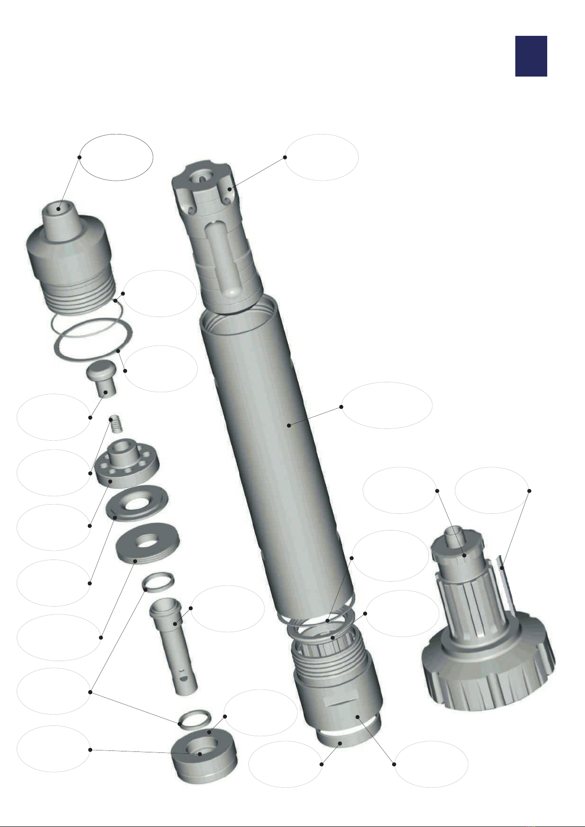
COMPONENT PARTS
1. First remove the chuck assembly. This comprises the button bit,
drive - plates (or drive pins with the SD 18 conversion), chuck release
washer, chuck ‘O’ ring, and bit retainers.
2. With the hammer laid horizontal, unscrew the backhead and
remove it from the wearsleeve. The valve chest along with the check
valve arrangement can now be pulled from the backhead end.
The remaining buffer cover, compression buffer and control tube
assembly can be removed by lifting the chuck end of the wearsleeve
which will allow the piston to push the parts up to the end face, from
where they can be removed by hand.
3. Lifting the Chuck end of the Wearsleeve again will allow the Piston
to slide to the end face from where it can be removed.
Backhead
Backhead ‘O’Ring
Breakout Washer
Check Valve
Check Valve Spring
Valve Chest
Buffer Cover
Check Valve
Compression Buffer
Control Tube
Assembly
Wearsleeve
Assuming both the chuck and the backhead threads
have been loosened either on the drilling rig or by using
a hydraulic splitter, the stripping procedure is as follows
NOTE:- All components must be washed clean and
laid out on a dirt free surface to enable inspection
to take place. The stripping procedure is explained
in the following section,
Note:- On no account should the wearsleeve be
impacted by a hand hammer or splitting be
assisted by use of localised heat: ie. welding/blow
torch, this will invalidate the warranty
Should splitting prove difficult, the breakout
washers can be ground out, taking care not to
deface other pieces of the drill, to relieve
pressure and help splitting,
Wearsleeve
Chuck
0.3” Breakout
Washer
STRIPPING THE HAMMER 6
0.300”
0.740”