
English
4. Electrical connection
The connection voltage and frequency must cor-
respond to the rated values quoted on the data
plate. The unit must be connected to the mains
via a disconnection device which ensures at least
3 mm contact opening in the deactivated state.
No additional temperature control must be con-
nected to the supply side of the unit. Line protec-
tion should be provided by means of the pre-fuse
specified on the name plate. Please observe the
relevant regulations when installing!
The mains connection is made at the connec-
tion terminal
5. Cooling water
connection
The cooling water connection must be made with
pressure resistant flexible hoses which should be
secured with clips.
(Note the direction of flow and check for
absence of leaks!)
The units have no separate air-bleed. With
pressure-sealed systems, corresponding air-
bleed facilities are to be installed on the water
side.
Protect the water circuit from contamination and
excess pressure (10 bar max.).
Please observe the relevant regulations when
installing!
6. Refrigeration and
control behaviour
The fan of the air circuit operates continuously,
thus ensuring an even temperature distribution
within the enclosure. A solenoid valve controls the
cooling water flow in accordance with the preset
temperature. Setting range +20°C to +60°C.
Presetting of the enclosure temperature is made,
6.1 for SK 3214.100 / SK 3215.100 /
SK 3216.480
via the thermostat on the rear of the unit.
6.2 SK 3212.xxx has no control unit.
7. Leaks and temperature
monitoring
7.1 Temperature monitoring
Should the temperature inside the enclosure rise
by more than
10 K in the models SK 3214.100 / SK 3215.100
SK 3216.480
For SK 3214.100 / SK 3215.100 / SK 3216.480
the connection of the potential-free contact is
made via the plug-in terminal strip on the rear of
the unit.
7.2 Leak monitoring
In the event of a leakage developing
a pipe fracture occurring in the water circuit
a) the cooling water supply will be cut
off immediately,
b) the potential-free changeover contact will
be switched, and
c) the fan will be switched off.
8. Maintenance
The air/water heat exchangers require no main-
tenance (see point 12.).
Check the function of the condensate draining
facility regularly.
9. Scope of supply
and warranty
3212.xxx / SK 3214.100 / SK 3215.100 /
SK3216.480
1 air/water heat exchanger, ready for connection
1 sealing tape
4 fastening bolts
(internal installation of unit 3247.000)
4 threaded pins M6 x 30
(internal installation of unit)
4 flat-headed screws M6*
4 fixing rings*
4 nuts M6
4 washers A 6.4
4 protective caps
1 set of assembly and operating instructions
1 drilling template
* Only for SK 3214.100 / SK 3215.100 /
SK 3216.480
instead of the threaded pins.
Guarantee:
This unit is covered by a 1-year guarantee from
the date of supply, subject to correct usage.
Within this period, the returned unit will be
repaired in the factory or replaced free of charge.
The unit is to be used for the cooling of enclosures
only. If it is connected or handled improperly the
manufacturer’s guarantee does not apply and in
this case we are not liable for any damage
caused.
Contents
1. Application
2. Technical data
3. Assembly
4. Electrical connection
5. Cooling water connection
6. Refrigeration and control behaviour
7. Leaks and temperature monitoring
8. Maintenance
9. Scope of supply and warranty
10. Safety instructions
11. Notes on water quality
12. Spares lis
1. Application
Air/water heat exchangers are designed and
built to dissipate heat from enclosures, by cool-
ing the air inside the enclosure and protecting
temperature sensitive components. Air/water
heat exchangers are particularly suitable for the
temperature range of +40°C to +70°C, where for
system related reasons, comparable units such
as air/air heat exchangers, enclosure cooling
units or fan units with filters cannot be used to
dissipate heat effectively and economically.
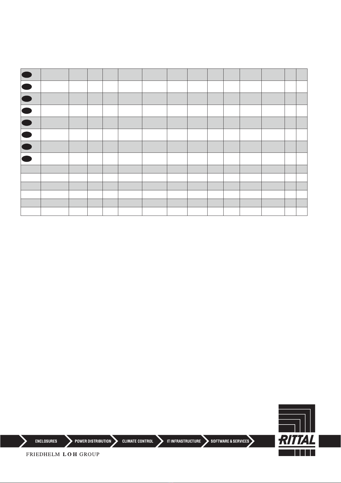
2. Technical data
(see table 2.1).
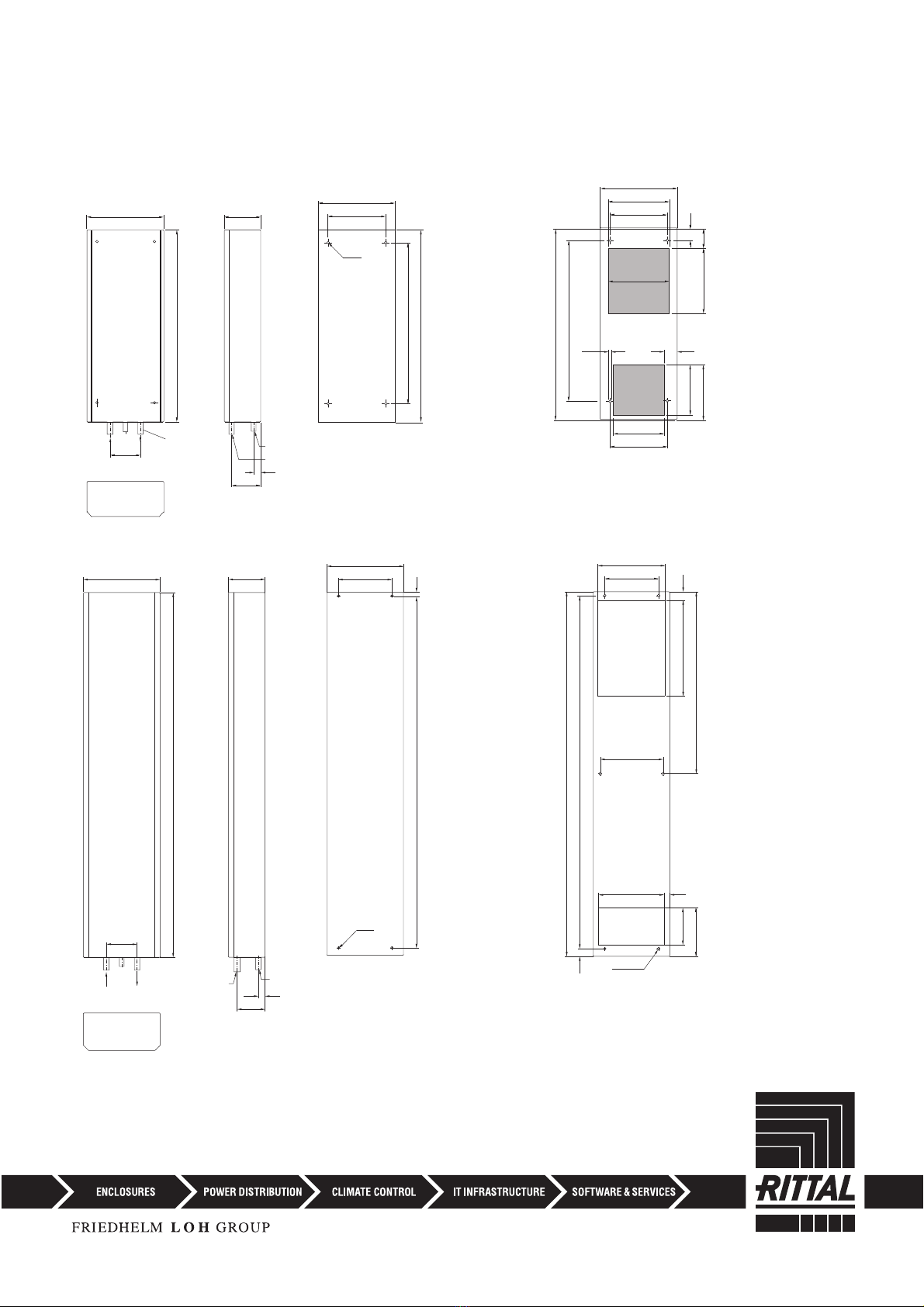
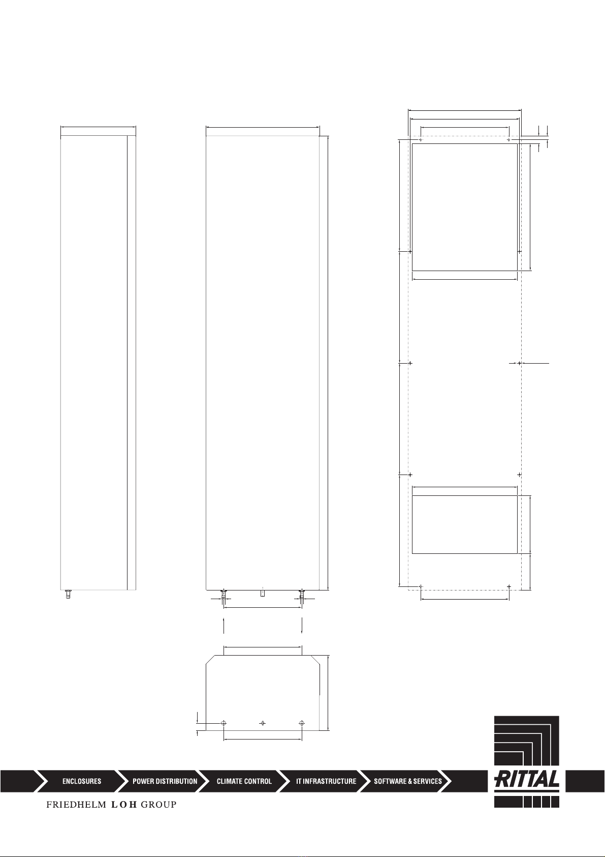
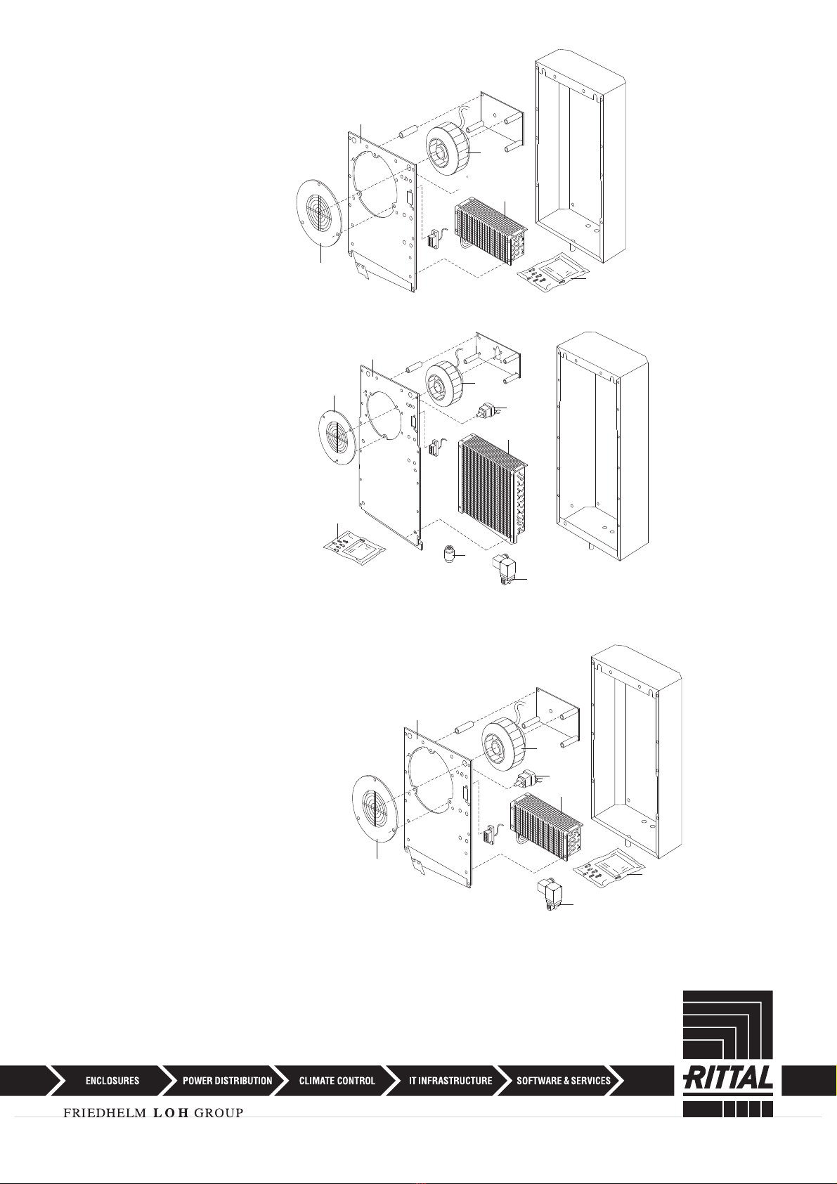
3. Assembly
Please use the enclosed drilling template to cut
out the component apertures.
SK 3212.230 / SK 3214.100 / SK 3215.100 / SK
3216.480
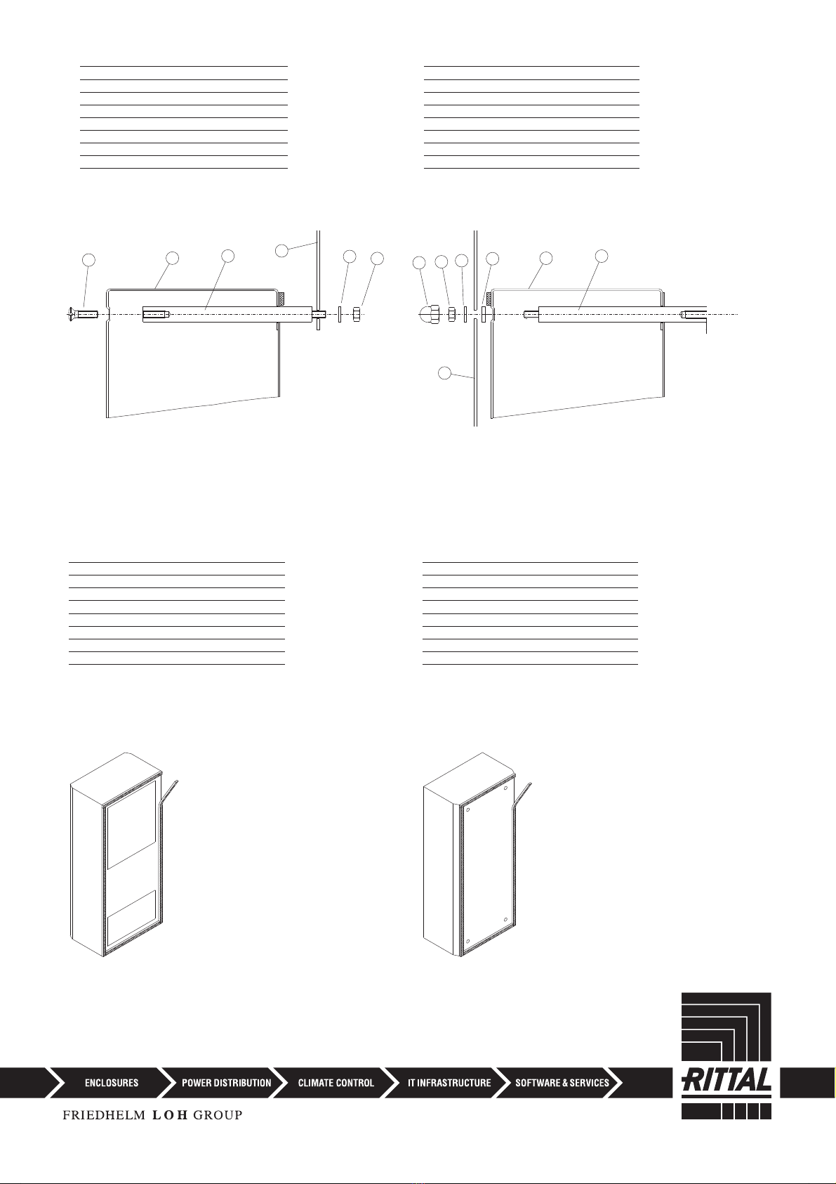
External installation of the unit
Screw the four fastening bolts ➀, together with
the washer ➁and nut ➂, to the mounting level
➃ of the enclosure. Push the heat exchanger ➄
into position and secure with four screws ➅.
Internal installation of the unit (Fig. page 30):
Insert four fastening bolts ➀into the appliance
from behind. Slide the fixing ring ➆onto the
fastening bolts as a mounting aid. Screw the
appliance, together with the washer ➁and nut
➂, to the mounting level of the enclosure from
the outside. Push the protective cap ➇onto the
nut.
10. Safety instructions
● When installing the device, the condensate
discharge must be routed out of the enclosure!
● In order to avoid frost damage, the minimum
permissible water temperature of +1°C must
not be undercut at any point in the water cycle!
● It is essential to obtain the manufacturer’s
permission before adding anti-freeze!
● During storage and transportation below
freezing point, the water cycle should be
drained completely using compressed air!
● Only set the thermostat as low as is strictly
necessary, because of undercutting the dew
point with a falling water inlet temperature
(condensation)!
● It is very important that the enclosure is sealed
on all sides (IP 54), particularly the cable entry
(condensation)!


 Guía de solución de problemas")


