Risco RVCM11H Manual de usuario

1
VUpoint Cube Indoor
IP Camera
Model: RVCM11H
Installation Guide

2
Safety Precautions
These instructions are intended to ensure that the user can use the product correctly to
avoid danger or property loss.
WARNINGS:
Installation or usage of this product that is not in accordance with the intended
use as defined by the supplier and as described in the instructional materials
can result in damage, injury, or death.
Ma e sure this product is not accessible by children and those for whom
operation of the system is not intended.
All installation and operation should conform to your local electrical safety
codes. The power shall conform to the requirement in the SELV (Safety Extra
Low Voltage) and the Limited power source is rated 12V DC in the IEC60950-1.
If the device is permanently connected to an electrical power supply, then the
connection should include an easily-accessible disconnection device, such as a
circuit brea er. Do not connect the two power supplying sources to the device
at the same time; it may result in device damage!
Do not ever attempt to repair your device by yourself, as doing so could result
in damage, injury or death – always contact your installer / supplier agent for
service.
CAUTIONS:
Ma e sure the power supply voltage is correct before using the camera.
Do not drop the camera or subject it to physical shoc .
Do not touch sensor modules with fingers. If cleaning is necessary, use a clean
cloth with a bit of ethanol and wipe it gently.
Do not aim the camera lens at the strong light such as sun or incandescent
lamp. The strong light can cause fatal damage to the camera.
The sensor may be burned out by a laser beam, so when any laser equipment is
being used, ma e sure that the surface of the sensor not be exposed to the laser
beam.
Do not place the camera in extremely hot, cold temperatures (the operating
temperature should be between -10°C ~ +50°C).
To avoid heat accumulation, good ventilation is required for a proper operating
environment.
Keep the camera away from water and any liquid.
While shipping, the camera should be pac ed in its original pac ing.
NOTE: We assume no liability or responsibility for all the fires or electrical shoc
caused by improper handling or installation. We are not liable for any problems caused
by unauthorized modification or attempted repair.

3
Introduction
RISCO Group presents VUpoint, a revolutionary live video verification solution
which seamlessly integrates I Cameras within RISCO’s professional security
systems. owered by the RISCO Cloud (RISCO Application Server), VUpoint
provides an unprecedented level of security and live video monitoring
capabilities to monitoring stations and end-users alike. The RISCO cube indoor
I Camera is an important part of this solution and
is easily controlled through
RISCO’s intuitive Web and Smartphone applications.
Features
•lug & lay installation
•1.3” Megapixel
•Color HD
•SD card slot for local storage
•WiFi
•IR LED (7-10m)
Components and Accessories
RISCO I camera and mounting bracket:
Electrical power adapter (not supplied with
the camera) and installation accessories bag:
Installation guide:
Minimum Internet Network Requirements:
•750 Kbps upload speed (per camera)
•5 Mbps download speed
RECOMMENDATION – You can install more than one camera with the
minimum recommended requirement (750 Kbps for each camera), but note that
viewing multiple cameras in parallel may reduce the refresh speed and picture
quality.

4
IP Camera Components and Dimensions
Figure 1 IP Camera Components
Label Port Name Indicator Connector Description
1 Power
indicator
light
POWER / When camera boots up – Green
light turns on.
When camera is upgrading – Green
light flashes.
Interval is 0.5s.
When camera is in alarm – Green
light flashes.
Interval is 0.2s.
2
Networ
indicator
light
NET / Wired networ connection - Red
light is on.
Wireless networ connection -
Green light is on.
3 Spea er / / Output audio signal (This function is
optional).
4 IR LED Red LED / During dar ness, the IR LED turns on
automatically.
5 N/A N/A N/A N/A
5
Label Port Name Indicator Connector Description
6 Microphone / / Directly receive audio signal (This
function is optional).
7 Micro SD
card
Micro
SD
Micro SD
card slot
SD card storage.
Micro SD card requirements
Type class 4
Memory up to 64GB.
NOTE: Adding micro SD card enables
the ability of recording video clips.
When entering/replacing micro SD card,
camera should be powered off.
8 Reset
button
Reset / Restore factory default setup. When
system is running normally, press the
RESET button for at least 5 seconds,
system can restore factory default setup.
9 WPS button WPS Fast
wireless
connection
Press the WPS button of the router and
the device respectively for at least 2
seconds. Usually the device connects to
the router within 1 minute.
Please note that this is for wireless router
with WPS functionality only.
1 N/A N/A N/A N/A
11 Power port DC12V / Input DC 12V power.
12 Network
port
LAN Ethernet
port
Connects to standard Ethernet cable.
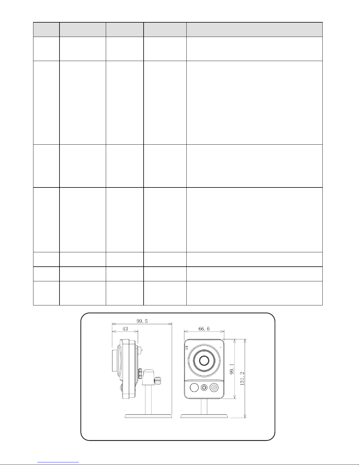
Figure 2 IP Camera Dimensions

6
IP Camera Installation
After reading the installation instructions and before installing your IP camera,
prepare a plan for mounting the IP camera at your protected site. Correct
placement of your IP camera is crucial for optimal security-monitoring
performance. First, determine which areas need to be protected and then map
out the most optimal areas for installing your IP camera.
IMPORTANT! – Please make a record of the AC
address located on the box or on the back cover of
the IP camera before installation. You may need it
during the network connection stage.
Mounting the IP Camera
The IP camera support two mounting options; ceiling and wall mount (see Figure
3 and Figure 4, below).
Figure 3 Ceiling Mount
Figure 4 Wall Mount
IMPORTANT- Please make sure the installation surface can support at least 3
times the weight of the camera and the bracket.
MAC address

7
Step Description
1 Place the installation positioning template on the installation surface such as
ceiling or wall.
2 Make holes in the installation surface according to the installation positioning
template.
3 Insert the expansion bolts from the accessories bag into the holes you just made.
4 Position the IP camera base over the holes
5 Use the screws from the accessories bag to secure the IP camera firmly.
6 Loosen the adjust knob and adjust the IP camera to the correct surveillance
position according to your actual requirements.
7 Secure the adjust knob to fix the IP camera.
Powering-up the IP Camera
1. Connect the provided electrical power adapter to the Power port on the IP
camera.
2. Connect the power adapter to an electrical outlet. When the IP camera boots
up, the GREEN power indicator light turns on.
Connecting the IP Camera to the Network
The IP camera supports several network connection options including LAN and
Wireless.
Connecting to a LAN Network
Connecting the IP camera to a network using the LAN (Local Area Network)
enables easy connection and setup with compatible APs (Access Points), e.g.
gateway or router.
1. Connect the incoming network cable to the Network port on the IP camera.
2. Wait just a few minutes while the IP camera automatically connects to the
RISCO Cloud. The RED network indicator light indicates that your IP camera
is now ready for defining camera settings (Refer to Defining IP Camera
Settings).

8
Connecting to a Wireless Network using WPS
Connecting the IP camera to a wireless network using WPS (Wi-Fi Protected
Setup) requires that the router and Operating System supports WPS
functionality.
NOTE – Some routers have a virtual button on their management software.
(Refer to the router’s documentation for details about using its WPS functions).
1. Once the power cord is connected, wait for 5 minutes for the camera to boot
up.
2. Press and hold down the WPS button on the IP camera and the WPS button
on the router respectively for 2 seconds. The GREEN network indicator light
indicates that your IP camera is now ready for defining camera settings
(Refer to Defining IP Camera Settings).
Connecting to a Wireless Network using the RISCO Cloud
Connecting the IP camera to a wireless network using the RISCO Cloud (RISCO
Application Server) requires that you first physically connect the IP camera to the
router and then, from the RISCO Cloud Installer Application, define the IP
camera settings and establish a wireless connection. Once a wireless connection
has been established the IP camera can then be disconnected from the router and
installed.
1. Connect the incoming network cable to the Network port on the IP camera.
2. Wait just a few minutes while the IP camera automatically connects to the
RISCO Cloud (RISCO Application Server). The RED network indicator light
indicates that your IP camera is now ready for defining camera settings
(Refer to Defining IP Camera Settings).
3. Once a wireless connection has been established, disconnect the IP camera
from the router and install it anywhere within the monitored area.
NOTES:
1. In order to connect the IP camera to RISCO Cloud via UPnP, the router should
be UPnP certified. If your router is not UPnP certified, we recommend not to use
UPnP and to open camera ports manually in the router (See Troubleshooting
section for more information).
2. The IP camera cannot be connected to more than one router.

9
IP Cameras and the RISCO Cloud Installer Application
The RISCO Cloud Installer Application provides an interface to your control
panel from a local or remote PC via the Web. This enables you to add IP cameras
and define camera and event alarm trigger settings.
IMPORTANT – A control panel must first be defined in RISCO Cloud in order
to accept IP cameras and define camera settings (Refer to the RISCO Cloud
Installer Application anual)
Defining IP Camera Settings
Once you have connected the IP camera to the network (refer to, Connecting the
IP Camera to the Network) you can define the camera settings.
To define IP camera settings:
1. Log into the Installer Administration application using the Web page address
supplied by your service provider and enter your user name and password.
NOTE – It is recommended to use Google Chrome or ozilla Firefox to log into
the Installer Administration application.
2. Select the Control Panels List link. The Control Panels List page is displayed.
Figure 5 Control Panels List Page
3. From the Control Panels List page, select the Control Panel you wish to view.
The Control Panels Update page is displayed.

10
Figure 6 Control Panel Update Page
4. Click the Network Cameras link in the left-hand column; the IP Camera List
page is displayed.
Figure 7 IP Cameras List
5. Click Add Camera; the Add Camera dialog box is displayed.
Figure 8 Add Camera
6. Define the following fields in the Add Camera dialog box.
Field Description
Label Enter a name for the camera
Partitions Select the partition(s) from the list of defined partitions
Type Choose the RISCO camera type (for ON
VIF or Generic camera type settings, refer to the RISCO Cloud Installer
Application Manual)
MAC
Address
Enter the MAC address into this field. The MAC address (media access
control address) is the unique identifier assigned to the IP camera for
communications on the physical network.
NOTE The MAC address is case sensitive and should be entered exactly as
it is shown on the box or on the back cover of the IP camera, e.g.
AA BB CC DD EE FF
Otros manuales para RVCM11H
2
Tabla de contenidos
Idiomas:
Otros manuales de Cámara IP de Risco

Risco
Risco RVCM52E Manual de usuario

Risco
Risco VUpoint RVCM52W Manual de usuario

Risco
Risco VUpoint RVCM61H03 Manual de usuario

Risco
Risco RVCM52E Manual de usuario

Risco
Risco eyeWAVE RWX95CM Manual de usuario

Risco
Risco eyeWAVE Manual de usuario

Risco
Risco RVCM11H Manual de usuario

Risco
Risco RVCM11H Manual de usuario


