
Rifox 1100 Manual de usuario

Operating Manual
RIFOX - Hans Richter GmbH Spezialarmaturen Fon: +49 (0) 421 499 75 - 0 Internet: www.rifox.de
06/2020 -Di. Subject to modifications
Page 1 of 6
Model: 1100
Float-Controlled Condensate Trap, PN 25
1 Safety instructions
1.1 Proper use
Any improper use, intervention in the design and deviation from the design data automatically lead to termination of the
warranty. The float-controlled condensate trap is designed for the discharge of condensate from steam, compressed air and
pressure gas systems. Any other usage is not permitted. The manufacturer is not liable for damage resulting from any other
usage. The user or operator bears the risk in this case. This also applies analogously to incorrect assembly, start-up, use and
maintenance.
1.2 Warnings and symbols
■Personal risk due to escaping operating medium because of pressure, temperature and weight. Failure to comply with
these warnings results in the risk of accidents.
■Follow the instructions in this operating manual.
■The operator must ensure that this operating manual and, if necessary, other relevant documents are available on site.
■Only trained or instructed personnel may be assigned to handling this equipment.
■Any mode of operation that may impair safety must be avoided.
2 General description and usage
2.1 Design of the condensate trap
1Housing flange part 11 Float with fork
2Housing gasket 12 Maxosglas
3Housing side part 13 RWG frame
4Control screw 14 2 gaskets for RWG
5Housing screws 15 RWG Screws
6Screw plug 16 Gasket
7Protective sleeve 17 Frame
8Supporting screw 18 Cutting ring threaded
joint
9Float control assembly 19 Gasket
10
Supporting body
assembly with rotary
valve and cotter pin
20 Gasket
Picture 1: Model 1100
1 7
9 611
10 20
18 17 12 13 15
14
8
19
RWG
Additional equipment
2.2 Operation limits of housing material (Design)
max. operating pressure (bar g) 25 23 20
max. operating temperature (°C) -10/120 200 300

Operating Manual
RIFOX - Hans Richter GmbH Spezialarmaturen Fon: +49 (0) 421 499 75 - 0 Internet: www.rifox.de
06/2020
Page 2 of 6
-Di. Subject to modifications
2.3 Function limit of control unit
Cross section max. line pressure in bar g
IIa 25
III 12
IV 11
V 2,5
VI 20
VIa 25
VII 18
VIIIa 4
VIIIb 4
2.4 Discharge capacity (for hot condensate)
For the cold condensate the discharge capacity is higher because of medium temperature and density.
2.5 Function
■Due to the gravity the condensate flows downwards to the lowest point, which is the condensate trap housing. In the
lowest position of the float the outlet cross-section is close. Rising of the liquid level lifts the float and opens the outlet.
Condensate will be discharged through the upturned immersion tube. Decreasing condensate level closes the outlet again.
2.6 Compensation line
■In order to get proper function, the non-condensable gas must be able to leave the housing. Due to the vertical installation,
the non-condensable gas is able to leave the housing and flows into the steam/gas chamber
above it, which has the same pressure level. If the self-venting through the pipe must be ex-
tended, the control screw (4) can be replaced by a cutting ring screw bolt and a compensation
line can be installed leading upwards.
2.7 Automatic venting
■RIFOka-automatic capsule venting valve (venting to interior): For start-up and permament
venting with high venting capacity. An special liquid inside the membrane capsule evaporates
and condenses only a few degrees below the boiling point of water. See Picture 3.
2.8 Gastight under-level float control (only for gas applications)
■For gas applications, a gastight under-level float control is nearly exclusively used. Consult with Rifox, if necessary.
Picture 3
capsule
Picture 2
Operating Manual
RIFOX - Hans Richter GmbH Spezialarmaturen Fon: +49 (0) 421 499 75 - 0 Internet: www.rifox.de
06/2020 -Di. Subject to modifications
Page 3 of 6
When using submerged-gastight control units, please note:
The valve orifice is always under an condensate surface.
If the gas is mixed or dissolved with the condensate, there can be no separation inside the steam trap.
Small amounts of gas can separate from the condensate at the outlet.
In these cases a degassing line at the outlet towards uncritical areas (via the roof for example) may be recommended.
A horizontal inflow can calm the condensate flow and support the self-degassing to separate the gas from the condensate.
When using an angular version (EF) condensate enters from above and can also bring gas into the housing.
With an inlet from below, the degassing happen before the trap, the automatic degassing is most effective.
Traps with submerged-gastight control units should not be used at above 90°C or its use should be clarified with RIFOX in
advance.
3 Assembly
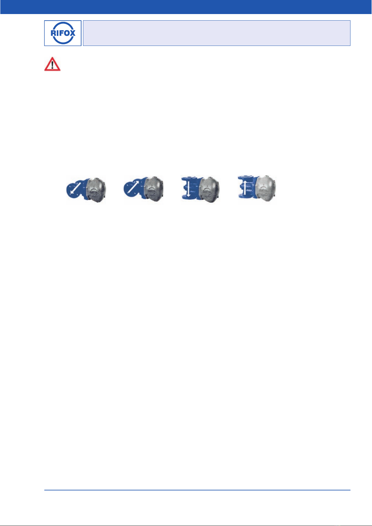
3.1 Flow Direction
Picture 4
Vario WR Vario WL Vario SO Vario SU
■Vario-WR: Flow direction horizontal from right to left
■Vario-WL: Flow direction horizontal from left to right
■Vario-SO: Flow direction vertical from top to bottom
■Vario-SU: Flow direction vertical from bottom to top
3.2 Modification for a different flow direction
The RIFOmat Vario 1100 is delivered according to the purchasing specification, as shown in Picture 5. It can be quickly
installed on site for a different flow direction, without any problem. Hier‘s an Example:
The RIFOmat Vario 1100 has been delivered as Vario-SU and has to be mounted as Vario-WR.
■Unscrew the housing hexagon nuts and remove the housing side part (3) sideways.
■Loosen the supporting screw (8) by unscrewing it for 1 - 2 full turns.
■Use a plastic hammer to loosen the float control assembly (9) from its conic housing seat by lightly stroking on the the
supporting screw (8) .
■Reposite the housing flange part (1) by turning it 90°.
■Reposite the float control assembly (9), so that the tube (T) pointing vertical downwards.
■Screw in the support bolt (8) with gasket (19). Tighten it with a standard ring wrench or a open jawed wrench, size 27.
Tightening torque according to Section 6.6.
■Replace the housing gasket (2) if damaged, and mount on the lateral part of housing side part (3).
■Tighten housing screws (5) evenly crosswise. Tightening torque according to Section 6.6.
3.3 Modification for restricted space and horizontal flow
In the case of only minimal space for the housing, which projects to the side, the housing side part (3) can be mounted to-
wards to the front or towards the rear by repositioning the housing flange part (1) for the purpose of better maintenance or
better visual inspection of a built-on reflective water level gauge, etc.

Operating Manual
RIFOX - Hans Richter GmbH Spezialarmaturen Fon: +49 (0) 421 499 75 - 0 Internet: www.rifox.de
06/2020
Page 4 of 6
-Di. Subject to modifications
3.4 Installation
■The condensate trap Vario 1100 has to be screwed into a pipeline between flanges.
■Remove transport caps from inlet and outlet.
■Fitting direction: according to Picture 5. The condensate flow is in the direction of the arrow (note the arrow on housing
flange part (1) ). The housing is positioned to the side. The word TOP on the housing side part is at the top and must be leg-
ible horizontally.
■Supporting brackets: The supporting brackets are not necessary for DN15/DN20/DN25 if the pipeline is adequately sup-
ported before and after the condensate trap. Condensate traps for DN40/DN50 weight over 34,5 kg, ensure thus proper fixing
of the pipeline in front of and behind the condensate trap.
■To avoid downtimes, it is recommended to install stop valves with bypass to pipeline, both in front of and behind the con-
densate trap.
4 Start-Up
The pressure build-up and heating-up of the housing should not take place abruptly. If leakage is detected after the first
inspection, the screws (4 / 5 / 6 / 8 / 15) can be fixed under consideration of the given torque moments, as given in Section
6.6. The screws can only be tightened on when the housing is unpressurized and at room temperature.
5 Observation and check
The function’s failure can be observed either as condensate blockage or as gas/ steam leakage.
■Condensate blockage can be determined by a): loosen the control screw (4) for a quarter rotation, while no condensate
leakage should occur; and by b): a surface thermometer on the housing for steam applications (if necessary, please consult
with Rifox).
■Gas / steam leakage: can be determined by an ultrasonic measuring device, and for steam applications by a surface
thermometer. In case of steam leakage, open the condensate trap according to Section 6.1. Make sure that float (11) can be
easily moved. If necessary, disassemble and clean the float control assembly (9). If damages/ wears are detected on parts or
on the sealing surface, the complete float control assembly (9) should be replaced.
6 Maintenance / Inspection
6.1 Opening the steam trap and dismantling the float control
■The steam trap must be depressurized. Shut off the system securely in front of and behind the steam trap.
■Release any remaining pressure in the housing by loosening the control screw (4) by only a quarter turn.
■Dismantle the steam trap from the pipeline system. Condensate traps for DN40/DN50 weight over 34,5 kg, apply thus
lifting device.
■Loosen the housing screws (5) evenly crosswise.
■Remove the housing side part (3).
■Loosen the supporting screw (8) and screw out 1 to 2 turns.
■With a few light strokes using plastic hammer on the front side of the supporting screw (8) to loosen the float control as-
sembly (9) from the conic housing seat.
■Screw out the supporting screw (8) completely. Take out the float control assembly (9).
6.2 Disassembling, cleaning and assembling the float control (Picture 5)
■After removing the cotter pin (p), the rotary valve (v) can be simply pulled out
to the side.
■Clean the parts using, for example, benzine.
■Check the rotary valve (v) for wear along the sealing edge. If wear is detected,
the support body (b) together with the rotary valve (v) must be replaced. The
exactly leakage test must be carried out by RIFOX.
■During assembly ensure that the notch in the rotary valve (v) points to the
punch mark on the support body (b) and the cotter pin (p) is inserted and secured
again carefully.
■It must be possible to move the float up and down easily by hand.
bpv
Picture 5

Operating Manual
RIFOX - Hans Richter GmbH Spezialarmaturen Fon: +49 (0) 421 499 75 - 0 Internet: www.rifox.de
06/2020 -Di. Subject to modifications
Page 5 of 6
6.3 Installation of the float control assembly and assemble the condensate trap
■The complete float control assembly (9) is inserted into the conical housing seat with the support body. It must be ensured
that the tube is positioned vertically downwards.
■Screw in the supporting screw (8) with gasket (19) and tighten evenly crosswise using a standard ring wrench. Tightening
torque according to Section 6.6.
■Check the housing gasket (2), replace it it is damaged.
■Put on the housing flange part (1).
■Tighten the housing screws (5) evenly crosswise. Tightening torque according to Section 6.6.
6.4 RIFOka automatic venting valve (Picture 6)
Function: Startup and continuous venting takes place inward, i.e. towards the conden-
sate side. Near the temperature of ebullition the capsule closes. When the temperature
drops, the capsule opens.
Replace the capsule (10.3):
■Dismantle the complete float control assembly (9) as described in Section 6.1.
■Loosen the hexagon nut (10.5) with wrench size 19.
■Screw up the support frame (10.4) for approx. 5 mm by turning it counterclockwise.
■Dismantle the capsule (10.3).
■Visual check the seat part of valve gate (10) and of capsule (10.3) for wear (cross scor-
ing).
■Replace the capsule (10.3). Marking S: down to 8 °C condensate supercooling.
■Screw support frame (10.4) against the capsule (10.3) using minimal manual force and align such that the support frame
(10.4) is positioned precisely in the crosswise.
■Hold support frame (10.4) in this position and lock hexagon nut (10.5) morately.
■Install the float control assembly (9) as described in Section 6.3.
6.5 Care and maintenance
■In the case of a great risk of dirt accumulation, the housing, when it is depressurized, should be rinsed thoroughly from
time to time. If necessary, the float control assembly (9) should also be checked according to Section 6.2.
■The dirt, which has been accumulated in the housing, can be removed away by screwing off the screw plug (6).
■For special applications, it is advisable to install a separate upstream strainer.
■The float control assembly (9) usually does not to be special maintained. The maintenance depends primarily on the wear
resistance of the valve gasket. See Section 6.1 and 6.2.
6.6 Tightening torque
Position Part Name Gasket
Tightening Torque (Nm)
DN15, DN20, DN25 DN40, DN50
4 Control screw Soft iron 40 40
5 Housing screw Soft iron 100 110
6 Screw plug Soft iron 120 120
8 Supporting screw Soft iron 110 110
15 RWG screw Novaphit SGBC 20 20
Picture 6
Capsule

Operating Manual
RIFOX - Hans Richter GmbH Spezialarmaturen Fon: +49 (0) 421 499 75 - 0 Internet: www.rifox.de
06/2020
Page 6 of 6
-Di. Subject to modifications
6.7 Spare parts
Only original spare parts can be used.
1Housing flange part: EN-GJS-400-18-LT (5.3103) 11 Float with fork: SS 1.4301 or 1.4571
2Housing gasket: Soft iron 12 Maxosglas: as per DIN 7081
3Housing side part: EN-GJS-400-18-LT (5.3103) 13 RWG frame: S 235 JR
4Control screw: G¼“ (BSP), SS 1.4104 14 2 gaskets for RWG: Soft material
5Housing screws: 8.8 acc. DIN 939/934 15 RWG Screws: A4-70, DIN 938/934
6Screw plug: G½“ (BSP), DIN 910 - 5.8 16 Gasket: Soft iron
7Protective sleeve: SS 1.4057 17 Frame: S 235 JR
8Supporting screw: SS 1.4104 18 Cutting ring threaded joint: C-Steel
9Float control assembly:
SS 1.4057 / 1.4112 / 1.4301 / 1.4104, or complete 1.4571 19 Gasket: Soft iron
9.2
Complete Float Control with built-on membrane capsule
venting device RIFOka:
SS 1.4057 / 1.4112 / 1.4301 / 1.4104 / VA-Hastelloy
20 Gasket: Soft iron
10 Supporting body assembly with rotary valve and cotter pin:
SS 1.4057 / 1.4112 / 1.4301 / 1.4104, or complete 1.4571
10.2
Complete Supporting Structure incl. rotary slide valve, cotter
pin and built-on RIFOka-membrane capsule venting device:
SS 1.4057 / 1.4112 / 1.4301 / 1.4104
1 7
9 611
10 20
18 17 12 13 15
14
8
19
RWG
Additional equipment
Additional equipment
Picture 7: 1100
10.2 10.3
11
09.2
capsule
7 Conformity assessment
The pressure equipment described is a pressure-keeping component in accordance with the Pressure Vessel Directive
2014/68/EU.
DN15, DN20, DN25: according to Art. 4, Subs. 3, no CE-Mark.
DN40, DN50: Conformity verified through the identifying mark: CE 0525.
A detailed declaration of conformity assessment according to PED is available as separate document. Please request if
necessary, if not attached.
Tabla de contenidos
Otros manuales de Bomba de calor de Rifox


Manuales populares de Bomba de calor de otras marcas


Mitsubishi Electric
Mitsubishi Electric PUZ-SWM60VAA Manual de usuario

Dimplex
Dimplex LI 16I-TUR Guía del usuario

Carrier
Carrier WSHP Open v3 Guía de configuración rápida

TGM
TGM CTV14CN018A Manual de usuario

Carrier
Carrier 38MGQ Series Manual de usuario

Kokido
Kokido K2O K880BX/EU Guía de solución de problemas

Viessmann
Viessmann VITOCAL 300-G PRO Type BW 2150 Guía rápida

Carrier
Carrier 48EZN Manual de usuario

Viessmann
Viessmann KWT Vitocal 350-G Pro Series Instrucciones de funcionamiento

Ariston
Ariston NIMBUS Manual de usuario

Weishaupt
Weishaupt WWP L 7 Guía del usuario

GE
GE Zoneline AZ85H09EAC Manual de usuario