Richiger EA-350 Manual de usuario

RICHIGER EA-350 UNLOADER
Parts list
Operator's Manual

1
Index
2
page
01. Warranty Policy and Certificate
page
02. 4
Technical specifications
5
03. page
Dimensions
604. page
Safety precautions
7
05. page
Switching from transport to work
1006. page
Attaching the bag
1407. page
Grain extraction procedure
08. 17
page
Ending grain extraction
09. 17
page
Emptying the last section of bag
10. 20
page
Detaching bag from roller
21
page
11. Back to transport mode
22page
12. Maintenance
13. 23
page
Lubrication chart
14. 25
page
The grain flow concept
15. 26
page
General indications for efficient operation
16. 31
page
Parts List

01
2
This warranty is expressly in lieu of any other warranties, express or implied, including any warranty of merchantability
or fitness for a particular purpose.
Buyer's sole and exclusive remedy under this warranty shall be limited to the repair, replacement or exchange of
warranted parts at our option, F.O.B. our factory, or designated service center, agent or representative. If the agent or
representative grants any warranty greater in scope or time period or labor allowance than that detailed herein,
RICHIGER MAQUINARIAS S.A shall not be liable beyond the herein stated limitations.
Equipment and accessories not of our manufacture are not covered by this warranty. Any claim with regards to
defective aforementioned equipment and accessories shall be submitted by RICHIGER MAQUINARIAS S.A to the
original manufacturers for analysis and subsequent non-approval or approval of repair, replacement or exchange, at
their option.
No special, incidental, consequential or other damages or contingent liabilities including, but not limited to, loss of life,
personal injury, loss of crops, loss due to fire or water damage, loss of business or business income, down time costs
and trade or other commercial loss arising out of the failure of product. The term product and products as used in this
warranty designates the whole finished unit in its entirety, i.e. the complete assembled machine, and/or all and every
individual component, part, equipment and accessory that forms said complete assembled machine.
Normal wear and tear associated with use is expressly excluded from this warranty.
No products shall be returned without prior authorization from RICHIGER MAQUINARIAS S.A
Buyers and their agents shall prepay all transportation charges for the return of such products to RICHIGER
MAQUINARIAS S.A or designated service center. There will be no acceptance of any charges for labor and/or parts
incidental to the removal and remounting of product repaired or replaced under this warranty.
This warranty does not cover conditions over which RICHIGER MAQUINARIAS S.A has no control including, without
limitation, contamination, pressures in excess of the recommended maximum, products damaged or subject to
accident, abuse or misuse after shipment from factory, products altered and repaired by anyone other than RICHIGER
MAQUINARIAS S.A factory personnel or representative or source approved by RICHIGER MAQUINARIAS S.A in
writing prior to commencement of said work.
The first buyer is responsible for proof of delivery date of product for the purpose of establishing warranty time of
validity. Warranty can continue for new user should the product be resold by the first buyer during valid period of
warranty, only if this situation is reported in writing, with enclosed documentation as proof of purchase. Warranty will
not be applicable if series number or other identification markers are erased, obliterated or otherwise altered.
.
.
.
.
Warranty terms
Warranty policy
Limitations on Warranty
Unit: Hydraulic-Mechanical Grain Bag Unloader
Model: EA-350
RICHIGER MAQUINARIAS S.A, located in Avellaneda 661, Sunchales, Santa Fe province, Argentina, warrants its
product EA-350 mechanical grain unloader from defects in materials and workmanship under normal operating
conditions and proper application, in accordance with the specifications for operation as described by the
manufacturer, for the period of 365 days from date of delivery to buyer.

3
Limitations on Warranty
Within 15 days after delivery to or receipt by the buyer of the product, the buyer shall inform the seller in writing if
product is found defective or short in any respect. Failure to so inform the seller or any use by buyer of product shall
constitute conclusive evidence that the seller satisfactorily performed and the buyer waives any right to reject the
product thereafter
The first buyer is responsible for proof of delivery date of product for the purpose of establishing warranty time of
validity. Warranty can continue for new user should the product be resold by the first buyer during valid period of
warranty, only if this situation is reported in writing, with enclosed documentation as proof of purchase. Warranty will
not be applicable if series number or other identification markers are erased, obliterated or otherwise altered.
The following are types of failures which are not attributable to defects in materials and/or workmanship and which
are not considered by RICHIGER MAQUINARIAS S.A as part of the warranty extended hereunder. This listing is by
way of example and is not intended to be exhaustive:
1) Product suffered damages attributable to accident, abuse, neglect or ignorance.
2) Product was not used in accordance with manufacturer's recommendations.
3) Product did not receive required maintenance.
4) Failure ensued after replacement of original parts without express consent of RICHIGER
MAQUINARIAS S.A , or modifications that in RICHIGER MAQUINARIAS S.A.’s judgment may have
affected performance, safety and/or dependability parameters.
5) Product was used in a manner or for a purpose for which it was not designed or intended to be used.
6) Incorrect mounting of external gears, pulleys.
7) Stripped splines or keyways on drive shafts.
8) Damage due to deterioration during periods of storage by the purchaser prior to operation.
9) Damage of any kind from erosive or corrosive action of any gases or liquids handled by the machinery.
10) Lack of or incorrect type of hydraulic fluid, lubricant, oil and/or grease.
11) Contamination of hydraulic fluid.
12) Operating beyond recommended maximum speeds, pressures and temperatures.
13) Repairs or disassembly by unauthorized personnel.
14) Misalignment of drive shafts, gears, sprockets and power driven elements.
15) Damage due to voltage spikes, static discharge, electrical storms, physical abuse, externally controlled
device failure and improper fusing.
.
.
Buyer inspection and acceptance

02
4
Technical specifications
Materials to be extracted All kinds of dry grains (wheat, sorghum, maize, sunflower, soybeans, rice,
etc.) and pelletized materials
Capacity Up to 300 tons/tour (*)
Minimum power: 60 CV
Tractor
PTO revolutions: 540 rpm
Extraction High clearance discharge auger, mechanical drive
Drive shaft w / shear bolt protection
PowerTransmission
Mechanical central discharge auger & cross augers
Tires 11 L15 – 10 ply
Extraction system Automatic bag pickup system
Working height hydraulically controlled
Bag slasher blade
Works mechanically and hydraulically
Adjustable working width
Tire pressure: 30 lbs./sq. in.
Total weight 2000 kg. (4400 lbs.)
(*) Work capacity can vary according to grain type, moisture content and other factors
Manufacturer reserves right to change specifications at any given time without previous notification

4850
2590
3270
5210
5870
5230
3050
6180
1200
3065
2630
1930
5
03
Dimensions in millimeters
Work position
Transport position

IMPORTANT
The operator should become familiarized with machine controls before attempting actual operation. Keep unit in
good working condition. Any modification could cause malfunctioning, potentially dangerous situations, or reduced
machine durability.
04
6
In order to obtain maximum performance from your grain bag unloader, we recommend you keep
the owner's manual in a handy place for quick consultation. Read the manual carefully before
attempting to unload grain from bags and pay special attention to operating and maintenance
instructions.
Safety precautions
For the operator
Before transporting the grain unloader, verify that:
a) The tow bar pin is properly secured
b) Check tire pressure
c) Check that wheel bolts are properly tightened
d) Attach safety chains between machine's tow bar and
tractor drawbar for added security on the road
Most accidents are caused by human error. Follow all safety procedures.
Make sure all people are safely positioned before starting tractor's engine and engaging
the PTO.
Keep unloader clean and sheltered when not in use. This diminishes risk of deterioration
and eventual failure.
Keep a fire extinguisher handy.
Decals with safety indications and warnings should be strictly heeded, kept in good
condition and replaced if necessary.
When towing the machine, drive with the utmost caution on public roads.
Keep hands, feet and clothing well away from moving parts.
Stop the tractor's engine before attempting a hands-on task on the unloader.

05
WARNING:
At no time during the unloading operation should anyone, except the operator standing at the
hydraulic controls, approach unloader or bag, and that includes both tractor and truck drivers.
Onlookers should keep a safe distance. And never allow anyone to lean against the bag: augers are
turning inside.
2) To the side of the machine, on the roller
cross beam, an array of three levers, a turn knob
and a pressure limiting valve control the
unloader's hydraulics. A decal attached next to
them (Fig. 1) shows each control's function.
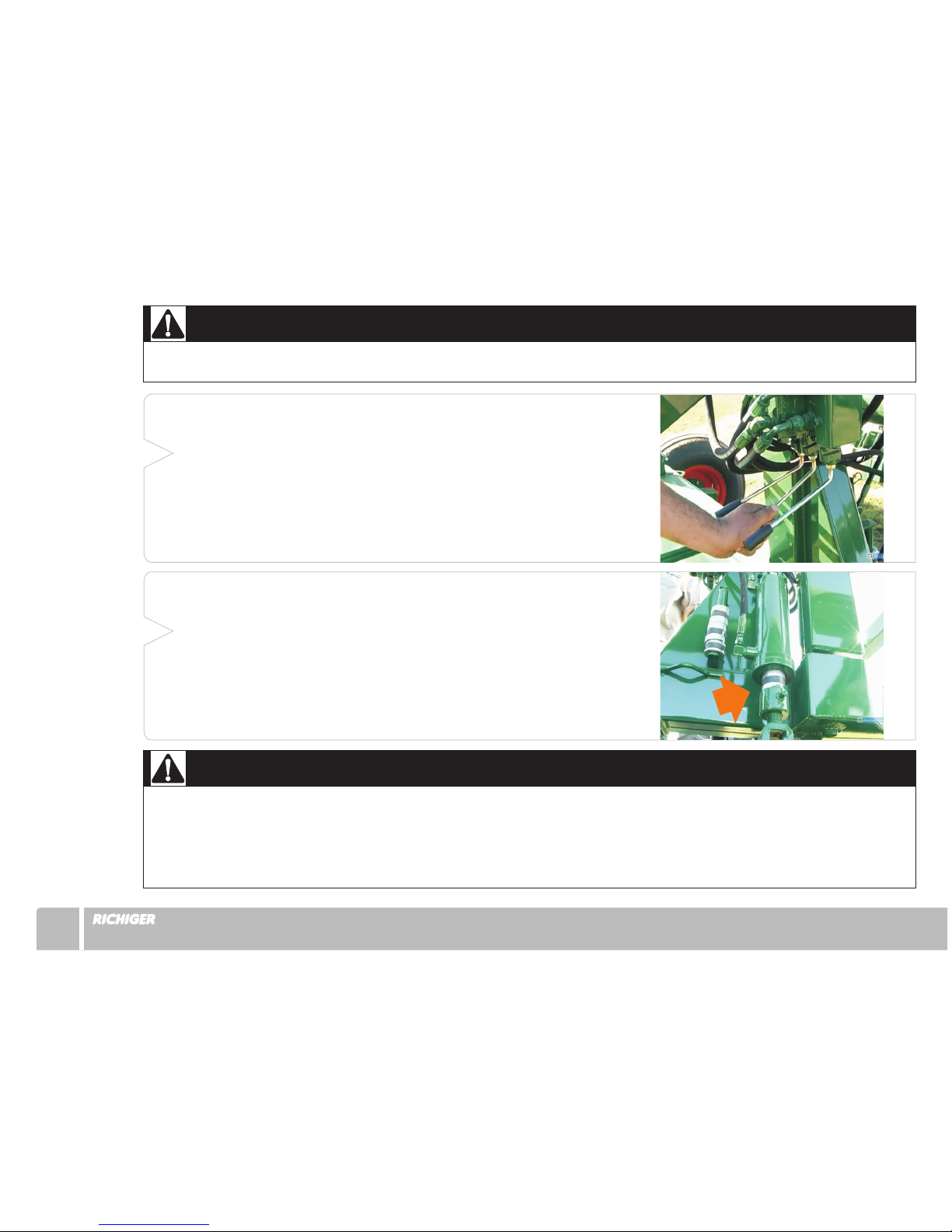
First step in preparing for work is raising the
discharge auger. With the tractor's hydraulics
turned on, move the first lever to its upward
position (Fig. 2). This will raise the auger tube
slowly.
As soon as auger is fully extended, move back
the lever to its mid (neutral) position. Once the
unloader has finished working and is to be towed
away, the sequence is reversed and the tube is
lowered by moving down the lever.
The sequence ends once the upper half is resting
firmly upon its transport prop and the control lever
is returned to neutral position.
1) Hitch tractor to unloader, connect hoses to
the tractor's hydraulic circuit and connect drive
shaft to the tractor's power take-off.
Fig.1
Fig.2
Switching from transport to work
7
NOTE:
A pressure limiting valve set to 850 PSI is provided as a safeguard against excessive pressure in the hydraulic circuit.
If this value is exceeded, oil will bypass the hydraulic motor and momentarily bring operation to a standstill.
Fig.3
Fig.4
8
3) Next, the second lever is used to regulate working
height (i.e., clearance of the sweep augers to the ground)
by means of a hydraulic cylinder. First, this center lever
should be moved to top position in order to raise the
unloader. To adjust for desired clearance, and the object
here is to set the sweep augers as close to the ground as
possible without scraping against it and compromising
bag integrity (see “General indications for efficient
operation” on page 26), a set of three clamp-on stops of
different size is provided.
Once a combination of stops or a single stop have
been selected and placed around the cylinder rod, the
control lever is pulled down (Fig. 3) so that the weight of
the unloader comes to rest upon the stops (Fig. 4). At this
point the lever is returned to its neutral position. The
height of the machine can be modified at any point, even
when the sweep augers are inside the bag.
IMPORTANT:
The unloader should not be raised or lowered with the hydraulic cylinder if the augers are deep within the grain mass,
as this could place undue strain on some components. The correct procedure is to release a few feet of plastic from
the roller by counter rotating it hydraulically, advance forward with tractor to extricate the sweep augers from the
grain, modify machine clearance with the hydraulic cylinder removing or adding stops as necessary, back the machine
once again into the bag to position the augers next to the grain, and reinitiate PTO and roller to continue unloading.

7) Lower the support stand and reinsert pin
at the base (Fig. 8).
5) Remove the pin at the base of the support stand,
swing the stand upward and attach temporarily to main
beam with same pin (Fig. 5).
4) The third lever, used to control roller rotation,is
not used at this stage.
6) Pull back the
spring-loaded pin that holds the
roller assembly in place during
transport and swivel it 90º to
work position (Figs. 6 & 7).
Fig.5
Fig.7
Fig.8
Fig.6
9
Tabla de contenidos
Otros manuales de Maquinaria agrícola de Richiger


Manuales populares de Maquinaria agrícola de otras marcas

GSi
GSi PNEG-2314 Manual de usuario

Checchi & Magli
Checchi & Magli TEXDRIVE Manual de usuario

Amazone
Amazone Cenius 4003-2TX Manual de usuario

MASSEY FERGUSON
MASSEY FERGUSON MF 9313S Manual de usuario

Cima
Cima BLITZ Instrucciones de funcionamiento y mantenimiento

Amazone
Amazone CombiDisc 3000 Instrucciones de instalación


