Rice Lake CLS-M Suplemento

CLS-M
Cargo Lift Scale
Installation/Service Manual
PN 126179 Rev LFebruary 26, 2019

An ISO 9001 registered company
© Rice Lake Weighing Systems. All rights reserved.
Rice Lake Weighing Systems® is a registered trademark of
Rice Lake Weighing Systems.
All other brand or product names within this publication are trademarks or
registered trademarks of their respective companies.
All information contained within this publication is, to the best of our knowledge, complete and
accurate at the time of publication. Rice Lake Weighing Systems reserves the right to make
changes to the technology, features, specifications and design of the equipment without notice.
The most current version of this publication, software, firmware and all other product
updates can be found on our website:
www.ricelake.com

Contents
© Rice Lake Weighing Systems ● All Rights Reserved i
Contents
Technical training seminars are available through Rice Lake Weighing Systems.
Course descriptions and dates can be viewed at www.ricelake.com/training
or obtained by calling 715-234-9171 and asking for the training department.
1.0 Introduction . . . . . . . . . . . . . . . . . . . . . . . . . . . . . . . . . . . . . . . . . . . . . . . . . . . . . . . . . . . . . . . . . . . . . . . . . . . . 1
1.1 Safety . . . . . . . . . . . . . . . . . . . . . . . . . . . . . . . . . . . . . . . . . . . . . . . . . . . . . . . . . . . . . . . . . . . . . . . . . . . . . . . . . . . . . . . . . . . . . 1
1.2 Considerations Before Installation . . . . . . . . . . . . . . . . . . . . . . . . . . . . . . . . . . . . . . . . . . . . . . . . . . . . . . . . . . . . . . . . . . . . . . . 2
1.2.1 Forklift Derating . . . . . . . . . . . . . . . . . . . . . . . . . . . . . . . . . . . . . . . . . . . . . . . . . . . . . . . . . . . . . . . . . . . . . . . . . . . . . . 2
1.2.2 Forklift Battery and CLS Installation. . . . . . . . . . . . . . . . . . . . . . . . . . . . . . . . . . . . . . . . . . . . . . . . . . . . . . . . . . . . . . . 3
1.3 Power/Communication Box Introduction . . . . . . . . . . . . . . . . . . . . . . . . . . . . . . . . . . . . . . . . . . . . . . . . . . . . . . . . . . . . . . . . . . . 3
1.4 Power/Communication Connection to Junction Box . . . . . . . . . . . . . . . . . . . . . . . . . . . . . . . . . . . . . . . . . . . . . . . . . . . . . . . . . . 3
1.5 iQube2TM CLS Junction Box . . . . . . . . . . . . . . . . . . . . . . . . . . . . . . . . . . . . . . . . . . . . . . . . . . . . . . . . . . . . . . . . . . . . . . . . . . . 4
2.0 Scale Base Installation . . . . . . . . . . . . . . . . . . . . . . . . . . . . . . . . . . . . . . . . . . . . . . . . . . . . . . . . . . . . . . . . . . . 5
2.1 Before Installation . . . . . . . . . . . . . . . . . . . . . . . . . . . . . . . . . . . . . . . . . . . . . . . . . . . . . . . . . . . . . . . . . . . . . . . . . . . . . . . . . . . . 5
2.2 Recommended Tools for Installation. . . . . . . . . . . . . . . . . . . . . . . . . . . . . . . . . . . . . . . . . . . . . . . . . . . . . . . . . . . . . . . . . . . . . . 5
2.3 Unpacking . . . . . . . . . . . . . . . . . . . . . . . . . . . . . . . . . . . . . . . . . . . . . . . . . . . . . . . . . . . . . . . . . . . . . . . . . . . . . . . . . . . . . . . . . . 6
2.3.1 Unpacking a One Scale Configuration . . . . . . . . . . . . . . . . . . . . . . . . . . . . . . . . . . . . . . . . . . . . . . . . . . . . . . . . . . . . . 7
2.3.2 Unpacking a Two Scale Configuration . . . . . . . . . . . . . . . . . . . . . . . . . . . . . . . . . . . . . . . . . . . . . . . . . . . . . . . . . . . . . 8
2.4 Scale Base Installation . . . . . . . . . . . . . . . . . . . . . . . . . . . . . . . . . . . . . . . . . . . . . . . . . . . . . . . . . . . . . . . . . . . . . . . . . . . . . . . . 9
2.5 Connect the Coiled Interface Cable to Junction Box. . . . . . . . . . . . . . . . . . . . . . . . . . . . . . . . . . . . . . . . . . . . . . . . . . . . . . . . . 11
2.6 Install Forks onto Scale Assembly . . . . . . . . . . . . . . . . . . . . . . . . . . . . . . . . . . . . . . . . . . . . . . . . . . . . . . . . . . . . . . . . . . . . . . 11
3.0 Power/Communication Box Hardware Setup . . . . . . . . . . . . . . . . . . . . . . . . . . . . . . . . . . . . . . . . . . . . . . . . 12
3.1 Mounting Locations . . . . . . . . . . . . . . . . . . . . . . . . . . . . . . . . . . . . . . . . . . . . . . . . . . . . . . . . . . . . . . . . . . . . . . . . . . . . . . . . . . 12
3.1.1 Mounting Location #1. . . . . . . . . . . . . . . . . . . . . . . . . . . . . . . . . . . . . . . . . . . . . . . . . . . . . . . . . . . . . . . . . . . . . . . . . 12
3.1.2 Mounting Location #2. . . . . . . . . . . . . . . . . . . . . . . . . . . . . . . . . . . . . . . . . . . . . . . . . . . . . . . . . . . . . . . . . . . . . . . . . 12
3.2 Mounting Power/Communication Box . . . . . . . . . . . . . . . . . . . . . . . . . . . . . . . . . . . . . . . . . . . . . . . . . . . . . . . . . . . . . . . . . . . . 13
3.2.1 Power/Communication Box (PN 153616) . . . . . . . . . . . . . . . . . . . . . . . . . . . . . . . . . . . . . . . . . . . . . . . . . . . . . . . . . 13
3.3 Power Cable Connection . . . . . . . . . . . . . . . . . . . . . . . . . . . . . . . . . . . . . . . . . . . . . . . . . . . . . . . . . . . . . . . . . . . . . . . . . . . . . 15
3.3.1 Power Cable to Battery Connection . . . . . . . . . . . . . . . . . . . . . . . . . . . . . . . . . . . . . . . . . . . . . . . . . . . . . . . . . . . . . . 16
3.4 Routing the Load Cell Coiled Interface Cable . . . . . . . . . . . . . . . . . . . . . . . . . . . . . . . . . . . . . . . . . . . . . . . . . . . . . . . . . . . . . . 18
3.4.1 Powering the Power/Communication Box (PN 153616). . . . . . . . . . . . . . . . . . . . . . . . . . . . . . . . . . . . . . . . . . . . . . . 19
3.5 Weights and Measures Sealing . . . . . . . . . . . . . . . . . . . . . . . . . . . . . . . . . . . . . . . . . . . . . . . . . . . . . . . . . . . . . . . . . . . . . . . . 19
4.0 Revolution® Interface to CLS . . . . . . . . . . . . . . . . . . . . . . . . . . . . . . . . . . . . . . . . . . . . . . . . . . . . . . . . . . . . . 20
4.1 Load USB Driver . . . . . . . . . . . . . . . . . . . . . . . . . . . . . . . . . . . . . . . . . . . . . . . . . . . . . . . . . . . . . . . . . . . . . . . . . . . . . . . . . . . . 20
4.2 Install Revolution. . . . . . . . . . . . . . . . . . . . . . . . . . . . . . . . . . . . . . . . . . . . . . . . . . . . . . . . . . . . . . . . . . . . . . . . . . . . . . . . . . . . 21
4.2.1 Download and Install Revolution from Rice Lake Website. . . . . . . . . . . . . . . . . . . . . . . . . . . . . . . . . . . . . . . . . . . . . 21
4.2.2 Install Revolution from CD . . . . . . . . . . . . . . . . . . . . . . . . . . . . . . . . . . . . . . . . . . . . . . . . . . . . . . . . . . . . . . . . . . . . . 24
4.3 Revolution Scale Software . . . . . . . . . . . . . . . . . . . . . . . . . . . . . . . . . . . . . . . . . . . . . . . . . . . . . . . . . . . . . . . . . . . . . . . . . . . . 27
4.3.1 USB Cable to Power/Communication Box . . . . . . . . . . . . . . . . . . . . . . . . . . . . . . . . . . . . . . . . . . . . . . . . . . . . . . . . . 27
4.3.2 Connect USB Card to the iQube2 Junction Box (PN 164071) . . . . . . . . . . . . . . . . . . . . . . . . . . . . . . . . . . . . . . . . . . 27
4.3.3 Connect Computer to Power/Communication Box. . . . . . . . . . . . . . . . . . . . . . . . . . . . . . . . . . . . . . . . . . . . . . . . . . . 28
4.4 Live Weight Data. . . . . . . . . . . . . . . . . . . . . . . . . . . . . . . . . . . . . . . . . . . . . . . . . . . . . . . . . . . . . . . . . . . . . . . . . . . . . . . . . . . . 30
4.5 Leveling Forklift Forks . . . . . . . . . . . . . . . . . . . . . . . . . . . . . . . . . . . . . . . . . . . . . . . . . . . . . . . . . . . . . . . . . . . . . . . . . . . . . . . . 31
4.6 EZ Setup/Upload Unit Serial Number . . . . . . . . . . . . . . . . . . . . . . . . . . . . . . . . . . . . . . . . . . . . . . . . . . . . . . . . . . . . . . . . . . . . 32
4.7 Software Version. . . . . . . . . . . . . . . . . . . . . . . . . . . . . . . . . . . . . . . . . . . . . . . . . . . . . . . . . . . . . . . . . . . . . . . . . . . . . . . . . . . . 34
4.8 Default Configuration . . . . . . . . . . . . . . . . . . . . . . . . . . . . . . . . . . . . . . . . . . . . . . . . . . . . . . . . . . . . . . . . . . . . . . . . . . . . . . . . 34
4.9 Diagnostics . . . . . . . . . . . . . . . . . . . . . . . . . . . . . . . . . . . . . . . . . . . . . . . . . . . . . . . . . . . . . . . . . . . . . . . . . . . . . . . . . . . . . . . . 35
4.9.1 Diagnostics Monitor . . . . . . . . . . . . . . . . . . . . . . . . . . . . . . . . . . . . . . . . . . . . . . . . . . . . . . . . . . . . . . . . . . . . . . . . . . 35
5.0 Calibration . . . . . . . . . . . . . . . . . . . . . . . . . . . . . . . . . . . . . . . . . . . . . . . . . . . . . . . . . . . . . . . . . . . . . . . . . . . . 38

CLS-M Installation/Service Manual
ii Visit our website www.RiceLake.com
Rice Lake continually offers web-based video training on a growing selection
of product-related topics at no cost. Visit www.ricelake.com/webinars
5.1 Leveling Forklift Forks . . . . . . . . . . . . . . . . . . . . . . . . . . . . . . . . . . . . . . . . . . . . . . . . . . . . . . . . . . . . . . . . . . . . . . . . . . . . . . . . 38
5.2 Carriage Junction Box Calibration Mode. . . . . . . . . . . . . . . . . . . . . . . . . . . . . . . . . . . . . . . . . . . . . . . . . . . . . . . . . . . . . . . . . . 39
5.3 Standard Calibration . . . . . . . . . . . . . . . . . . . . . . . . . . . . . . . . . . . . . . . . . . . . . . . . . . . . . . . . . . . . . . . . . . . . . . . . . . . . . . . . . 39
5.3.1 Standard Calibration with Linear Points . . . . . . . . . . . . . . . . . . . . . . . . . . . . . . . . . . . . . . . . . . . . . . . . . . . . . . . . . . . 48
5.3.2 Reading Data in Live Weight Screen . . . . . . . . . . . . . . . . . . . . . . . . . . . . . . . . . . . . . . . . . . . . . . . . . . . . . . . . . . . . . 56
6.0 Load Cell Replacement and Flexure Troubleshooting. . . . . . . . . . . . . . . . . . . . . . . . . . . . . . . . . . . . . . . . . 57
6.1 Required Tools for Replacing a Load Cell . . . . . . . . . . . . . . . . . . . . . . . . . . . . . . . . . . . . . . . . . . . . . . . . . . . . . . . . . . . . . . . . 57
6.2 Load Cell Replacement. . . . . . . . . . . . . . . . . . . . . . . . . . . . . . . . . . . . . . . . . . . . . . . . . . . . . . . . . . . . . . . . . . . . . . . . . . . . . . . 58
6.3 Forklift Flexure Troubleshooting - 28" and 34" Models . . . . . . . . . . . . . . . . . . . . . . . . . . . . . . . . . . . . . . . . . . . . . . . . . . . . . . . 64
7.0 iQube2® Junction Box . . . . . . . . . . . . . . . . . . . . . . . . . . . . . . . . . . . . . . . . . . . . . . . . . . . . . . . . . . . . . . . . . . 65
7.1 iQube2 Junction Box Replacement. . . . . . . . . . . . . . . . . . . . . . . . . . . . . . . . . . . . . . . . . . . . . . . . . . . . . . . . . . . . . . . . . . . . . . 65
7.2 Download the Serial Number to the Junction Box. . . . . . . . . . . . . . . . . . . . . . . . . . . . . . . . . . . . . . . . . . . . . . . . . . . . . . . . . . . 67
7.3 iQube2 PCB Board Assembly Replacement. . . . . . . . . . . . . . . . . . . . . . . . . . . . . . . . . . . . . . . . . . . . . . . . . . . . . . . . . . . . . . . 69
7.4 iQube 2.3 Cross References. . . . . . . . . . . . . . . . . . . . . . . . . . . . . . . . . . . . . . . . . . . . . . . . . . . . . . . . . . . . . . . . . . . . . . . . . . . 70
8.0 Power/Communication Board Replacement . . . . . . . . . . . . . . . . . . . . . . . . . . . . . . . . . . . . . . . . . . . . . . . . . 71
8.1 Bluetooth PCB Field Replacement Instructions . . . . . . . . . . . . . . . . . . . . . . . . . . . . . . . . . . . . . . . . . . . . . . . . . . . . . . . . . . . . 73
9.0 Spare Parts and Troubleshooting . . . . . . . . . . . . . . . . . . . . . . . . . . . . . . . . . . . . . . . . . . . . . . . . . . . . . . . . . 74
9.1 Parts Breakout . . . . . . . . . . . . . . . . . . . . . . . . . . . . . . . . . . . . . . . . . . . . . . . . . . . . . . . . . . . . . . . . . . . . . . . . . . . . . . . . . . . . . 74
9.2 Troubleshooting Table . . . . . . . . . . . . . . . . . . . . . . . . . . . . . . . . . . . . . . . . . . . . . . . . . . . . . . . . . . . . . . . . . . . . . . . . . . . . . . . 84
9.3 Troubleshooting iQube2 LEDs . . . . . . . . . . . . . . . . . . . . . . . . . . . . . . . . . . . . . . . . . . . . . . . . . . . . . . . . . . . . . . . . . . . . . . . . . 88
9.4 RS-232/Bluetooth LED Functionality and Troubleshooting. . . . . . . . . . . . . . . . . . . . . . . . . . . . . . . . . . . . . . . . . . . . . . . . . . . . 89
9.5 Power/Communication Box Troubleshooting . . . . . . . . . . . . . . . . . . . . . . . . . . . . . . . . . . . . . . . . . . . . . . . . . . . . . . . . . . . . . . 90

Introduction
© Rice Lake Weighing Systems ● All Rights Reserved 1
1.0 Introduction
This manual is for trained and qualified personnel responsible for installing and servicing the CLS-M. This manual covers
information on the installation and service of the scale carriage, coiled interface cable and the power/communication box.
Manuals are available for viewing and/or downloading from the Rice Lake Weighing Systems website at
www.ricelake.com/manuals
Warranty information can be found on the website at www.ricelake.com/warranties
1.1 Safety
Safety Signal Definitions:
Indicates an imminently hazardous situation that, if not avoided, will result in death or serious injury. Includes
hazards that are exposed when guards are removed.
Indicates a potentially hazardous situation that, if not avoided, could result in serious injury or death. Includes
hazards that are exposed when guards are removed.
Indicates a potentially hazardous situation that, if not avoided, could result in minor or moderate injury.
Indicates information about procedures that, if not observed, could result in damage to equipment or corruption
to and loss of data.
General Safety
Do not operate or work on this equipment unless this manual has been read and all instructions are understood.
Failure to follow the instructions or heed the warnings could result in injury or death. Contact any Rice Lake
Weighing Systems dealer for replacement manuals.
Failure to heed could result in serious injury or death.
Some procedures described in this manual require work inside the power/communication box. These procedures are to be
performed by qualified service personnel only.
Take all necessary safety precautions when installing the scale carriage including wearing safety shoes, protective eye wear, and
using the proper tools.
Do not allow minors (children) or inexperienced persons to operate this unit.
Do not operate without all shields and guards in place.
Do not jump on the scale.
Do not use for purposes other then weight taking.
Do not place fingers into slots or possible pinch points.
Do not use any load bearing component that is worn beyond 5% of the original dimension.
Do not use this product if any of the components are cracked.
Do not exceed the rated load limit of the unit.
Do not make alterations or modifications to the unit.
Do not remove or obscure warning labels.
Do not use near water.
Keep hands, feet and loose clothing away from moving parts.
DANGER
WARNING
CAUTION
IMPORTANT
WARNING
CLS-M Installation/Service Manual
2 Visit our website www.RiceLake.com
1.2 Considerations Before Installation
1.2.1 Forklift Derating
1.2.1.1 Capacity Reduction Calculation
The CLS fits most typical forklifts, but there are considerations that must be taken into account prior to installation. Due to the
extra weight of the CLS, the net lifting capacity of the forklift is reduced by approximately 10%. Use the formula below to
calculate the amount to down-rate the lifting capacity and determine the net capacity of the forklift.
Figure 1-1. CLS Capacity Formula
1.2.1.2 CLS Classes and ID Plates
An updated ID plate on the forklift stating the new lifting capacity and center of gravity information is required per OSHA rules
and regulations.
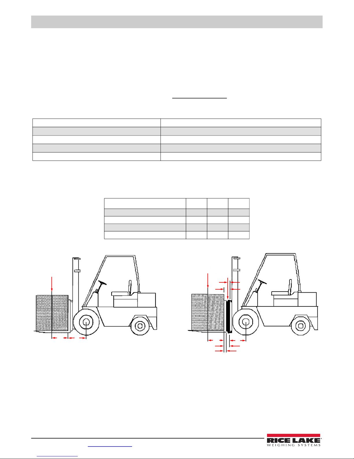
Figure 1-2. Forklift CLS Reference
A = Truck Basic Capacity in pounds B = Inches from front wheel center line to fork face
C = Inches from face to truck rating point (usually 24) D = Weight of scale in pounds
E = Inches from front wheel center line to carriage face F = Inches from carriage face to scale horizontal center of gravity (HCG)
G = J + K (inches from carriage face to rear face of load H = Inches from fork face to new truck rating point
J = Thickness of fork K = Thickness of scale
Table 1-1. CLS Capacity Formula Key
28"34"38"
Vertical enter of gravity (VCG) of scale 8.06 8.06 10.15
Horizontal center of gravity (HCG) of scale 2.09 2.09 2.83
Effective thickness (ET) of scale 4.55 4.55 6.06
Effective thickness (ET) of scale 392 420 987
Table 1-2. CLS Forklift ID Plate Dimensions
Net Capacity A (B + C) - D (E + F)
E + G + H
=
CB
AD
G
F
Net
Capacity
HE
K
J

Introduction
© Rice Lake Weighing Systems ● All Rights Reserved 3
1.2.2 Forklift Battery and CLS Installation
Take into consideration that the indicator power source is connected directly to the battery of the forklift. Most
typical is 12 volts for propane, gas and diesel forklifts.
12 volt systems must have a negative ground, ensure the forklift has a negative ground electrical system. The
CLS cannot operate on a positive ground forklift. Refer to the forklift manual to verify grounding requirements.
Standard CLS scales use 9-36 V power supply for use on 12 V batteries. Install the following for electric system forklifts:
PN 166162 – DC-DC Converter, CLS
PN 166161 – Power Line Filter, CLS (for static protection)
1.3 Power/Communication Box Introduction
The Power/Communication box transmits data between the scale and the hand-held device. The Mac ID label is used to pair
the CLS Bluetooth® interface with the hand-held device supplied by the customer.
Figure 1-3. Power/Communication Box Schematic (PN 153616)
1.4 Power/Communication Connection to Junction Box
The Power/Communication box receives data from the junction box through the Interface Cable.
Figure 1-4. Interface Cable – Power/Communication Box to Junction Box
CAUTION

CLS-M Installation/Service Manual
4 Visit our website www.RiceLake.com
1.5 iQube2TM CLS Junction Box
The latest CLS Series scales includes an updated version of the iQube2 junction box. This design is built to allow service
technicians to easily service the unit in the field. Below is an overview of the new features and functions.
It also replaces the older style junction boxes, originally used in the CLS Series scales.
Figure 1-5. iQube2 Junction Box
** Allows for connection to Revolution from the front of the forklift, using Type B USB micro connector. A built-in USB driver
allows easy interface capabilities. Simply connect to Revolution and select the new USB COM port generated. This can help
eliminate the coiled cable and communication/power box. If updating firmware, switch to a USB Micro A connector.
Figure 1-6. iQube2 Junction Box Component Parts
Coiled Cable
Connection
Mild Steel
Construction
Field Replaceable
Load Connectors
Calibration Switch ** Type B USB micro connector for
use with Revolution or USB Micro A
connector for firmware updates
Field Replaceable Load
Cell Connectors
Gortex Vent
Optional Load Cell
Sealing Kit (PN 167226)
Field Replaceable Coiled
Cable Connector
Field Replaceable Load Cell
Connectors

Scale Base Installation
© Rice Lake Weighing Systems ● All Rights Reserved 5
2.0 Scale Base Installation
This section describes procedures for installing the Cargo Lift Scale base.
Take all necessary safety precautions when installing the scale carriage, including wearing safety shoes and
protective eyewear, and using the proper tools, which are listed in Section 2.4.
The Cargo Lift scale is shipped from the factory with the scale already calibrated and all settings stored in the junction box.
Minimal adjustments and calibration might be necessary once the scale is installed onto the forklift. Those calibration steps are
contained in Section 5.3 on page 39.
2.1 Before Installation
Before installing the CLS on a forklift, the forklift should be in good operating condition for optimal weighing accuracy. Look for
the following items prior to installing the CLS onto a forklift:
• Inspect the forks for any damage
• Check the locking pin on the forks for proper function
• Check and adjust the lift chain so the heel of the forks have 1/2 to 1 inch of clearance from the floor when the carriage is
down and the mast is vertical
• The slot for the center pin should be clear of grease and debris
• The top cleats of the forklift rest on the top of the scale and should remain clear of grease and debris that could alter the
scale’s performance
The power/communication box will be connected directly to the battery of the forklift. The CLS scale works with 9-36 VDC
power source.
All systems must have a negative ground.
2.2 Recommended Tools for Installation
Ensure the forklift meets the qualifications specified in Section 1.2 on page 2. Use the following tools to install onto the forklift:
Tool Size Purpose of Tool
Allen wrench 4 mm For service only, to remove junction box
Crescent wrench 2'' adjustable For adjusting the shim bolts and jam nuts
Tin snips or band cutters NA To cut the plastic banding surrounding the CLS while on the pallet
Torque wrench w/ 1/2" Allen 1/2'' To tighten the cleats to 125 ft-lb
Electric grinder For grinding the center pin if necessary and the mounting bolts
Wrench 7/16'' To connect power/communication box to mounting plates
Wrench & socket 9/16'' To connect mounting plates to forklift carriage
USB Type A to Type B Cable 6' Use with laptop for access to Revolution software for diagnostics, calibration and displayed weight
Level NA To perform angle zero calibration
Fish tape 6' Route power cable to forklift battery
Crimping tool NA Battery connections
Table 2-1. Recommended Tools for Installation
WARNING
CAUTION

CLS-M Installation/Service Manual
6 Visit our website www.RiceLake.com
2.3 Unpacking
If any parts were damaged in shipment, notify Rice Lake Weighin Systems and the shipper immediately.
The CLS is shipped upright on a sealed pallet with one or two scales per pallet.
Figure 2-1. CLS-M Packaging
Upon receipt of the shipping pallet, inspect it for any visible signs of damage. Immediately after unpacking, visually inspect the
contents to ensure all components are included and undamaged. The shipping pallet should contain the following:
1. One or two scale carriage assemblies with cover plate.
2. Hardware component boxes, which include:
A. Two cleats with four bolts.
B. One interface cable.
C. One power cable and hardware for battery connection.
D. One power/communication box.
E. One mounting kit for power/communication box with hardware.
To ensure that all products received from the manufacturer are in good shape upon arrival, it is recommended to
fully inspect all contents and properly fill out the bill of lading.
Hardware
Component
Boxes
Note
Otros manuales para CLS-M
2
Tabla de contenidos
Otros manuales de Máquina elevadora de Rice Lake


