Rhotheta RT-1000 Manual de usuario

User Manual
RT-1000
Antenna
VHF Bearing-System

RT-1000 Antenna
RHOTHETA Page 2 of 30 User Manual
Edited by:
RHOTHETA Elektronik GmbH
Kemmelpark
Dr.-Ingeborg-Haeckel-Str. 2
82418 Murnau
Germany
Tel.: +49 8841 4879 - 0
Fax: +49 8841 4879 - 15
Internet: www.rhotheta.de
E-Mail: [email protected]
Copyright © RHOTHETA Elektronik GmbH
All rights reserved
-Issue: 2016/11/04 [Rev 1.01.a]
-Document-ID: 12-9-2-0019-3-1-60
Note
The manufacturer reserves the right to make modifications at any time and without previous
information of the here described product.

RT-1000 Antenna
RHOTHETA Page 3 of 30 User Manual
Content
1
General Information.........................................................................................................4
1.1
Reflections and their Influence to the Bearing Result. ...........................................................................5
1.2
Influence of the signal ground reflection to the DF accuracy.................................................................9
2
Antenna Construction...................................................................................................14
2.1
Side View..............................................................................................................................................14
2.2
Bottom View..........................................................................................................................................15
2.3
Component List.....................................................................................................................................16
3
Assembly Instructions ..................................................................................................17
4
North Alignment of the Direction Finder Antenna and Determining the System
Accuracy at the Installation Site .........................................................................................19
4.1
North Alignment Using a Ground Transmitter (Pre-setting) .................................................................19
4.2
Flight Checking for Exact North Alignment and Determining the System Accuracy at the Antenna
Installation Site...............................................................................................................................................21
4.2.1
Determining the Position Using a Theodolite ..........................................................................22
4.2.2
Determining the Position Using a GPS Receiver ....................................................................22
4.2.3
Simplified Method ....................................................................................................................22
4.3
Evaluation.............................................................................................................................................23
4.3.1
Evaluation of Direction Finding Signal.....................................................................................23
4.3.2
Evaluation of QDR Live Display (Green Light Dot Circle) .......................................................25
4.3.3
Evaluation of Measuring Results.............................................................................................26
4.4
Determining the North Correction.........................................................................................................28
5
Mechanical Dimensions................................................................................................29
6
Notes...............................................................................................................................30

RT-1000 Antenna
RHOTHETA Page 4 of 30 User Manual
1 General Information
DF-Systems are used to locate aircraft, ships, vehicles or persons who have a radio
transmitter. All prevalent DF-Systems determine the direction from which the signal reaches
the DF-Antenna. If this direction is the same as the direction to the aircraft, vessel or the
vehicle, everything is fine. If the radio signal arrives, the DF-Antenna not in a direct way,
because of shadowing or reflections, the direction finder shows in the direction to the
reflector, where the signal (or the majority of the signal) comes from.
This direction can have a big difference to the direction of the source of the signal, the aircraft,
the vessel or the vehicle where the transmitter is located. The operator will regard this as a
malfunction of the direction finder. In the physical way, this is not true. The problem is that the
bearing we get from the DF is not the information the operator desires.
This means for the praxis, that we have to find an antenna location, where the radio signals
always arrive the antenna in the direct way.
The achievable bearing accuracy depends largely on the physical conditions at the antenna
location.
The remote concept of the RT-1000 C DF-System separates the antenna and the high
frequency components (RF-Antenna, Receiver Unit) from the controller side (Controller) with
the signal processing. So it is easy to place the antenna somewhere in the open field where
the physical conditions are good, while the Controller is located at the tower side.
The following information should help you, to find a physical convenient antenna location.
RT-1000 Antenna
RHOTHETA Page 5 of 30 User Manual
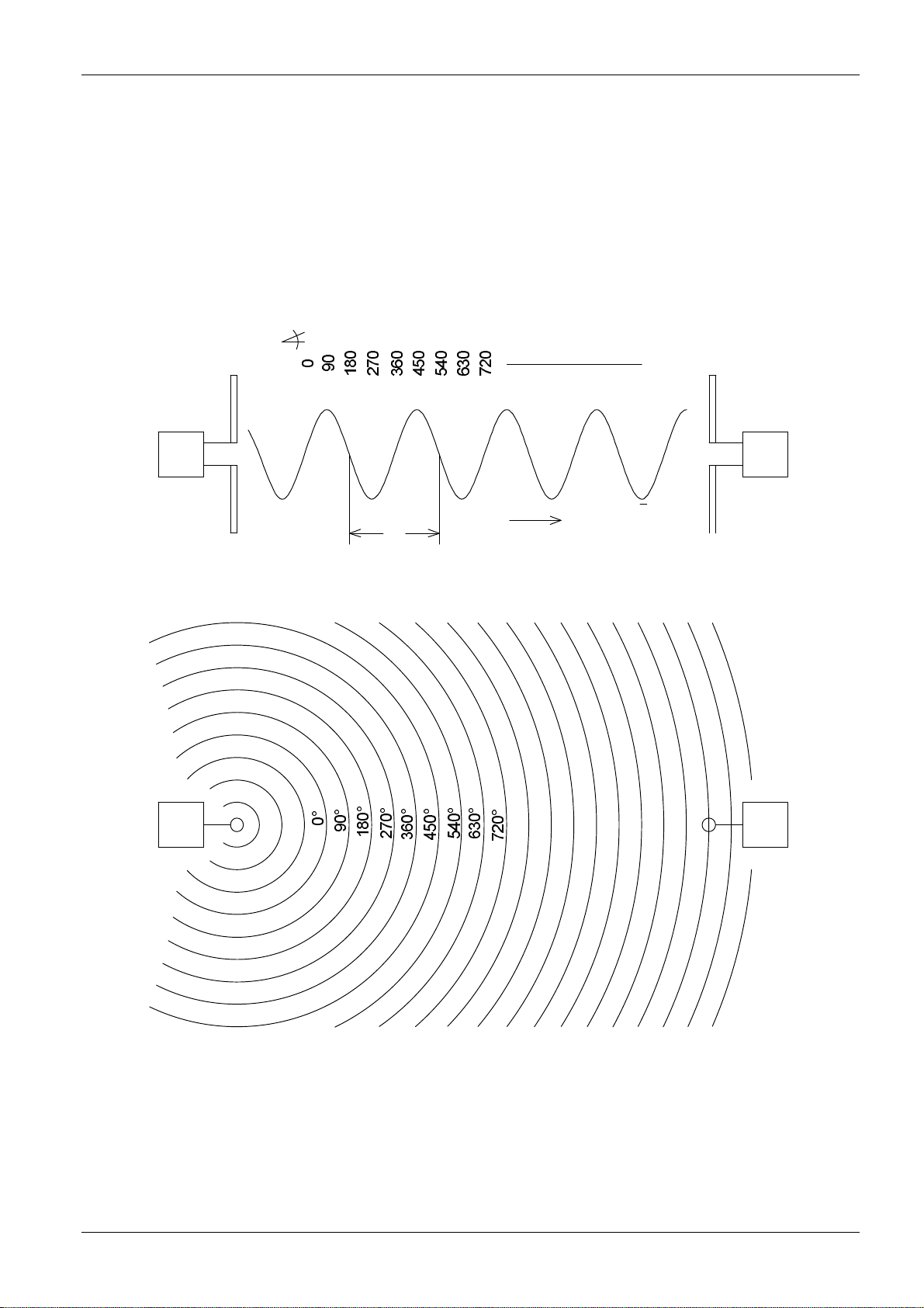
1.1 Reflections and their Influence to the Bearing Result.
The antenna of a DF-System can be seen as a sensor, which analyses the incoming
electromagnetic wave field to find out where it comes from. As the waves on quiet water
surface also radio waves in the free (unobstructed) field dispread circular from around the
transmitter.
Sender Empfänger
Sender Empfänger
Dipol Dipol
Weg
0 0 0 0 00 0 0 0 0
+ + + + +
-
bei v = c
Grad
Isophasen
a)
b)
---
v = Ausbreitungsgeschwindigkeit
c = Lichtgeschwindigkeit
= Wellenlänge
λλ
Fig. 1: Free-space propagation of radio waves
Fig. 1 gives an extremely simplified representation of even radio wave propagation in free
space. The sine wave in part a) corresponds to the instantaneous value of the electric field on

RT-1000 Antenna
RHOTHETA Page 6 of 30 User Manual
the plane path to the receiver. Part b) is the vertical projection of part a). The circles represent
the lines of equal phase relations for even waves.
If the distance between transmitter and receiver is adequate, these are practically straight
lines when they reach the receiver location. Such an idealized situation is not to be found in
built-up areas, and especially not in mountainous regions. In such areas, the propagation path
is obstructed by obstacles, mirror reflectors; diffuse reflectors with and without absorption
characteristics, diffracting edges and resonators. Reflectors and conducting rods are effective
as resonators if their size is approximately that of the wavelength to be received. Therefore,
reflections increase as wavelengths become shorter, diffractions at edges however are
reduced and so the effect of shadowing obstacles is more important.
Accordingly, the propagation characteristics of radio waves from approximately λ< 10 m
increasingly resemble those of light.
At a wavelength of 1 m to 3 m, wave propagation requires a direct path and if this is not
available, only reflected waves are received. In urban areas, these may come from several
directions simultaneously. But that is not all: the mostly horizontal or vertical plane polarized
waves propagated by the transmitter are also rotated to a certain degree due to diffuse
reflectors and diffracting edges. When the wave arrives at the receiver, it may be oblique,
elliptically, or even circular polarized. This fact becomes apparent by the often curious
antenna positions which are necessary to obtain the best reception of radio or television
waves.
These points are meant to indicate that in the VHF, UHF range, direction finding of a
stationary transmitter using a stationary direction finder in a built-up area or even inside a
building is practically impossible.
Transmitter Reflection
2
Fig. 2: Field of lines of equal phase relations for two coherent waves

RT-1000 Antenna
RHOTHETA Page 7 of 30 User Manual
Conditions at airports are much more favourable. These instructions are intended to allow the
best positioning of the direction finder antenna.
Of course, airports are not without reflectors, but these do not normally cause noticeable
problems. All direction finders with field probes calculate the angle of signal incidence by
finding out the path direction (vector), at which the largest phase modification per unit of
distance is present.
In Fig. 1 this vector is vertical to the lines of equal phase relations. Fig. 2 shows the distorted
field of lines of equal phase relations for two coherent waves (reflection) from different
directions with different field strengths.
Mainly 4 parameters influence the deviation of the bearing caused by reflections:
1. Position of the DF antenna
2. Position for the Transmitter antenna
3. Position of the reflector
4. Wave length of the signal (signal frequency)
The advantage of wide base direction finders is most noticeable in static conditions. Static
conditions indicate that the position of the transmitter and direction finder as well as the
transmitter frequency does not change with time. Should one of the three named items
change (e.g. transmitter in aero-plane) the direction finder antenna and the field of lines of
equal phase relations begin to move in relation to one another. This movement accelerates in
proportion to the relationship between the reflected path distance and the direct path distance
of the radio wave (Fig. 3).
As shown in Fig. 2, this movement in the case of wide base direction finders causes slight
azimuth oscillation. In contrast, this oscillation is larger in the case of narrow base direction
finders - the series of small circles in Fig. 2. When several values are averaged out however,
both systems give the same azimuth.

RT-1000 Antenna
RHOTHETA Page 8 of 30 User Manual
R1
R2
W1 W2
Reflector
Aeroplane
Direction finder
W2 W1
Reflector
Aeroplane
R1
R2
a) b)
Direction finder
Fig. 3: Reflected path distance an direct path distance of the radio wave
favourable: unfavourable:
W1/W2 » R1/R2 W1/W2 ≈R1/R2
With moving transmitter:
Rapid phase shifting between W and Only very slow phase shifting between W and
R signal, therefore good bearing average. R signal, so no averaging possible. The
possible displayed bearing oscillates slowly
around the rated value.
The following conclusions can be drawn:
Vertical reflector surfaces e.g. buildings, hangars, metal fences, metal masts, overhead
lines as well as bushes and trees should not be within 100 m of the direction finder
antenna if possible.

RT-1000 Antenna
RHOTHETA Page 9 of 30 User Manual
1.2 Influence of the signal ground reflection to the DF accuracy
The signal out of an aircraft transmitter will reach the DF antenna on the direct way. In
addition a part of the signal will be reflected on the ground and will reach the antenna as well.
Depending on the angle of incidence and the height at which the DF antenna is located above
the ground, the direct signal and the reflected signal have to go different distances.
W
W
W
R
R
R
R
R
R
W
Ground
Ground
h = large
h = small
unfavourable
favourable
a)
b)
A moving transmitter causes rapid
phase shifts between W and R signals
and therefore a lot of amplitude
fluctuations at the direction finder.
A moving transmitter causes slow
phase shifts between W and R signals
and therefore few amplitude fluctuations
at the direction finder.
Fig. 4: The phases between a direct wave W and a reflected wave R
This is the reason why there are angles of the signal incidence, where the signals are in
phase and there are angles where the signal arrive the antenna in opposite phase. On one
case the direct and the ground signal add each other, on the other case the direct signal is
compensated or reduced by the ground reflected signal. This is the reason why the vertical
antenna diagram become more zero points as higher the antenna is placed (see Fig. 5).

RT-1000 Antenna
RHOTHETA Page 10 of 30 User Manual
Vertical diagram for h = 23 m Vertical diagram for h = 3.5 m
Fig. 5: Signal strength lobes plotted against angle of elevation
The zeros of the vertical diagram can be determined using the following formula:
n
h
2
tan
λ
α
=
; f
c
0
=
λ
;
s
m
c
299792458
0
=
c
0
= light velocity [m/s]
λ= wave lengths of the signal [m]
h = height of the antenna head above the ground [m]
n = ordinal numeral of the zero point (1. 2. 3….)
f = signal frequency [Hz]
Otros manuales para RT-1000
7
Este manual sirve para los siguientes modelos
1
Tabla de contenidos
Otros manuales de Radio marina de Rhotheta

Rhotheta
Rhotheta RT-1000 Manual de usuario

Rhotheta
Rhotheta RT-1000 Manual de usuario

Rhotheta
Rhotheta RT-1000 Manual de usuario

Rhotheta
Rhotheta RT-1000 Manual de usuario

Rhotheta
Rhotheta RT-1000 Manual de usuario

Rhotheta
Rhotheta RT-1000 Manual de usuario

Rhotheta
Rhotheta RT-300 Manual de usuario

Rhotheta
Rhotheta RT-1000 Manual de usuario


