Rentquip patron GI-3500 Manual de usuario

operation manual
INVERTER
GI-3500
GENERATOR
5
safety
The safety alert symbol ( ) is used with a signal word (DANGER,
CAUTION, WARNING), a pictorial and/or a safety message to alert
you to hazards.
DANGER you WILL be KILLED or SERIOUSLY HURT if you don’t
follow instructions.
WARNING you CAN be KILLED or SERIOUSLY HURT if you don’t
follow instructions.
CAUTION you CAN be HURT if you don’t follow instructions
NOTICE your generator or other property could be damaged if you
don’t follow instructions.
Save these Instructions
SAFETY WARNINGS
This is the safety alert symbol. It is used to alert
you to potential personal injury hazards. Obey
all safety messages that follow this symbol to
avoid possible injury or death.
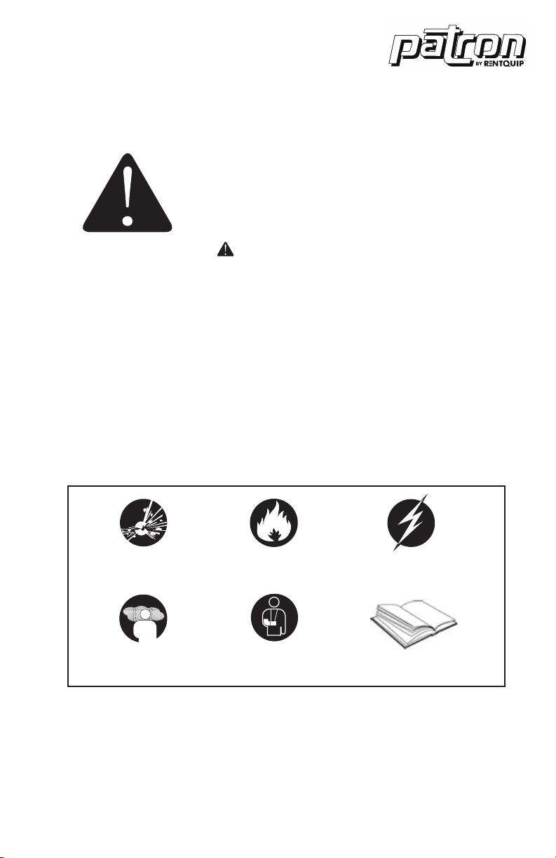
Hazard Symbols and Meanings
explosion
kickback read manual
fire electric shock
toxic fumes

6
safety
SAFETY INFORMATION
Read and understand this owner’s manual before operating your
generator. It will help you avoid accidents if you get familiar with your
generator’s safe operation procedures.
DANGER
Do not use indoors.
DANGER
Keep the machine clean and avoid spilling combustibles
including gasoline on it.
WARNING
Do not use in a wet condition.
WARNING
• Turn the generator “OFF” when adding fuel.
• Don’t add fuel near the flammable thing or cigarette.
• Keep children and pets away from the area of operation. Do not place
flammable objects close to the exhaust when generator operation.
Keep it at least 1m away from inflammables.
• The generating set must not be connected to other power sources,
such as the power company supply main. Protection against electrical
shock depends on circuit breaker specially matched to the generating
set. Due to high mechanical stresses only, tough rubber sheathed
flexible cable (in accordance with ICE 245 or the equivalent should be
used. When using extension lines or mobile distribution networks the
total length of lines for a cross section of 1.5 mm should not exceed
60 m; for a cross section of 2.5 mm this should not exceed 100 m.
Electrical equipment (including lines and plug connections) should
not be defective.
• Utilize safe proper grounding. Use the ground wire with enough
electric flux. Ground wire diameter: 0.12mm/A.
• The generator surface has high temperature, avoid scalding. Pay
attention to the warnings on the generating set.

7
safety
CONNECTION TO A HOME POWER SUPPLY
If the generator is to be used as standby home power supply the
connection is to be performed by a qualified electrician. When loads
are connected to the generator, carefully check whether electrical
connections are safe and reliable. Any improper connection may cause
damage to the generator or cause a fire.
• Keep generator at least 3ft (1m) away from buildings or other structures.
• Only operate generators in a dry, well ventilated area.
• Keep exhaust pipe clear of foreign objects.
• Keep generator away from open flame. No Smoking!
• Keep generator on a stable and level surface.
• Do not block generator air vents with paper or other material.
DO NOT place any heavy objects on the generator. Select and place the
generator in the proper position of the transport vehicle so that the
generator will not move or fall down. Secure the generator if necessary.

8
safety
UNIT SAFETY SYMBOLS
There is the warning label on the machine to remind you of the safety
regulations.
SYMBOLS
Read the safety instructions before using the generator.
Only fill the generator in well-ventilated areas and keep
it away from open flames sparks and cigarettes Spilled
fuel should be soaked up immediately.
Switch off the engine and let it cool down before filling
the generator Fuel is easily flammable and may even
explode under certain circumstances.
Gases such as carbon monoxide (colourless and
odorless gas) are produced during operation which
may lead to suffocation. Only use the generator in well
ventilated areas.
Warning! Dangerous voltages are present when the
generator is in operation. Generator must always be
switched off before performing maintenance works.
Wear ear protection when operating the generator.
Disconnect all devices from the connections before
performing maintenance work before leaving the device
and after switching it off.
The generator may not be connected to the public pow-
er supply When the device is falsely connected there is
a risk of fire material damage and even a fatal electric
shock being suffered by the operator as is also the case
when performing works on the public power supply.

9
control function
1. Fuel tank cap
2. Handle
3. Control panel
4. Inverter parts
5. Battery
6. Brake
7. Recoil starter grip
8. Shutter
9. Muffler
10. Oil drain bolt
11. Oil filler cap
12. Air cleaner
13. Carburetor
14. Spark plug
15. Left cover
16. Oil observation window
Control Function
DESCRIPTION
CONTROL PANEL
120V
1. AC receptacle
2. AC receptacle
3. AC circuit breaker
4. Multimeter
5. 3 in 1 switch knob
6. DC protector
7. DC receptacle
8. Electric Start
9. ESC (engine start control)
10. Parallel receptacle
11. Ground terminal

10
control function
1. Engine/fuel valve OFF”; Ignition
circuit is switched off. Fuel is switched
off. The engine will not run.
2. Engine switch\fuel valve choke.
“ON” Ignition circuit is switched on. Fuel
is switched on. Choke is switched on.
The engine will run.
3. Engine switch\fuel valve\choke.
“ON” Ignition circuit is switched on. Fuel
is switched on. Choke is switched on.
The engine can be start.
TIP: The choke is not required to start a
warm engine
1. “ON”
When the ESC switch is turned to
“ON”, the economy control unit controls
the engine speed according to the
connected load. The results are better
fuel consumption and less noise.
2. “OFF”
When the ESC switch is turned to
“OFF”, the engine runs at the rated
(3100r/min) Regard-less of whether is a
load connected or not.
TIP: The choke is not required to start a
warm engine
3 IN 1 SWITCH KNOB
ENGINE SMART CONTROL

11
control function
Liquid crystal display
Normal Operation:
During the normal operation, the
operation key (3) for switching the display
cycle showing: voltage current power-
accumulative time current time.
In case of failed operation:
U> a: AC over voltage, indicating the
character of AC (alternative indication of
AC and digit)
b: DC over voltage, indicating the
character of DC (alternative indication of
DC and digit)
U< a: AC under-voltage, indicating the
character of AC (alternative indication of
AC and digit)
b: DC under-voltage, indicating the
character of DC (alternative indication of
DC and digit)
I> Output over current of generator
Output short circuit of generator
Over heat of generator
Maintenance time
DIGITAL DISPLAY METER
1. Multimeter
2. Liquid crystal display
3. Operating key
4. Oil warming light
5. Overload indicator light
6. AC pilot light
When the oil level falls below the lower level,
the oil warning light comes on and then the
engine stops automatically. Unless you refill
with oil, the engine will not start again.
TIP: If the engine stalls or does not start, turn
the engine switch to “ON” and then pull the
recoil starter. If the oil warning light flickers for a
few seconds, the engine oil is insufficient. Add
oil and restart.
OIL WARNING LIGHT

12
control function
The overload indicator light comes on when
an overload of a connected electrical device
is detected, the inverter control unit overheats,
or the AC output voltage rises. Then, the AC
protector will trip, stopping power generation
in order to protect the generator and any
connected electric devices. The AC pilot light
(Green) will go off and the overload indicator
light (Red) will stay on, but the engine will not
stop running. When the overload indicator
light comes on and power generation stops,
proceed as follows:
1. Turn off any connected electric devices and
stop the engine.
2. Reduce the total wattage of connected
electric devices within the rated output.
3. Check for blockages in the cooling air Inlet
and around the control unit. If any blockages
are found remove.
4. After checking, restart the engine.
TIP: The overload indicator light may come on
for a few seconds at first when using electric
devices that require a large starting current,
such as a compressor or a submergible pump.
However, this is not a malfunction.
The AC pilot light comes on when the engine
starts and produces power.
OVERLOAD INDICATOR LIGHT (RED)
AC PILOT LIGHT (GREEN)

13
control function
The DC protector turns to “OFF” automatically
when electric device being connected to the
generator is operating and current above the
rated flows. To use this equipment again, turn
on DC protector by pressing its button to “ON”.
1. “ON” Direct current is output.
2. “OFF” Direct current is not output.
Ground (Earth) terminal (1) connects the earth
line for prevention of electric shock. When the
electric device is earthed, always the generator
must be earthed.
DC PROTECTOR
GROUND (EARTH) TERMINAL
NOTICE
• Reduce the load of the connected electric device below the speci-
fied rated output of the generator if the DC protector turns off. If the
DC protector turns off again, stop using the device immediately and
consult a franchised dealer.
This is the terminal for connecting special
cables for parallel running of two generator.
The parallel running requires two generator
and the special cables. (The rated output in
parallel running is 6.0Kva and the rated current
is 60A/100V;50A/120V;26A/230V.)
The handing, operation procedure and the
notes on usage are described in the PARALLEL
RUNNING KIT OWNER’S MANUAL included
in the Parallel.
During the operation and idle period of
machine, brake timely and switch to “STOP”.
In case of the machine is required to be moved,
switch the brake to “RUN”.
PARALLEL OPERATION OUTLETS
BRAKE
Tabla de contenidos
Otros manuales de Generador portátil de Rentquip


