REI HD5 Manual de mantenimiento
HD5 Maintenance
Quick Guide
© 2020 Radio Engineering Industries, Inc.

HD5 System Maintenance Check 2
HD5 System Maintenance Check Radio Engineering Industries, Inc. | 6534 L Street | Omaha, NE 68117
© 2020 Radio Engineering Industries, Inc. 800.228.9275 | p: 402.339.2200 | f: 402.339.1704 | radioeng.com
Table of Contents
1Introduction 3
2System Maintenance Check 4
3Laptop Setup when Using a Web User Interface 8
4Conduct Ping Test to Verify Connectivity 10
5HD5 Maintenance Check Off Sheet 12

HD5 System Maintenance Check 3
HD5 System Maintenance Check Radio Engineering Industries, Inc. | 6534 L Street | Omaha, NE 68117
© 2020 Radio Engineering Industries, Inc. 800.228.9275 | p: 402.339.2200 | f: 402.339.1704 | radioeng.com
1Introduction
This document outlines the step-by-step process for conducting a system maintenance check for HD5
series DVRs.
SERVICE HOT LINE
USA & CANADA
1-877-726-4617 Toll Free
1-402-339-2200

HD5 System Maintenance Check 4
HD5 System Maintenance Check Radio Engineering Industries, Inc. | 6534 L Street | Omaha, NE 68117
© 2020 Radio Engineering Industries, Inc. 800.228.9275 | p: 402.339.2200 | f: 402.339.1704 | radioeng.com
2System Maintenance Check
The vehicle must be powered on.
Assure the DVR is in record mode by checking that the hard drive is locked in the DVR. The REC light is
illuminated when this occurs.
REC Light Indicates Record Mode is Active
The monitor video cable and the USB mouse should be plugged in the front of the DVR. Refer to Section 3 if the
web interface is being used for setup information.

HD5 System Maintenance Check 5
HD5 System Maintenance Check Radio Engineering Industries, Inc. | 6534 L Street | Omaha, NE 68117
© 2020 Radio Engineering Industries, Inc. 800.228.9275 | p: 402.339.2200 | f: 402.339.1704 | radioeng.com
Video Should Appear on Active Channels
Assure there is video appearing on all the activated channels. If a blue screen appears, it could be caused by the
following:
•The camera is not plugged in
•The camera is not working
•The port needs to be turned off
Open the OSD window. Right click on the Setup button and select System Settings.
Check the ID, time, and date.
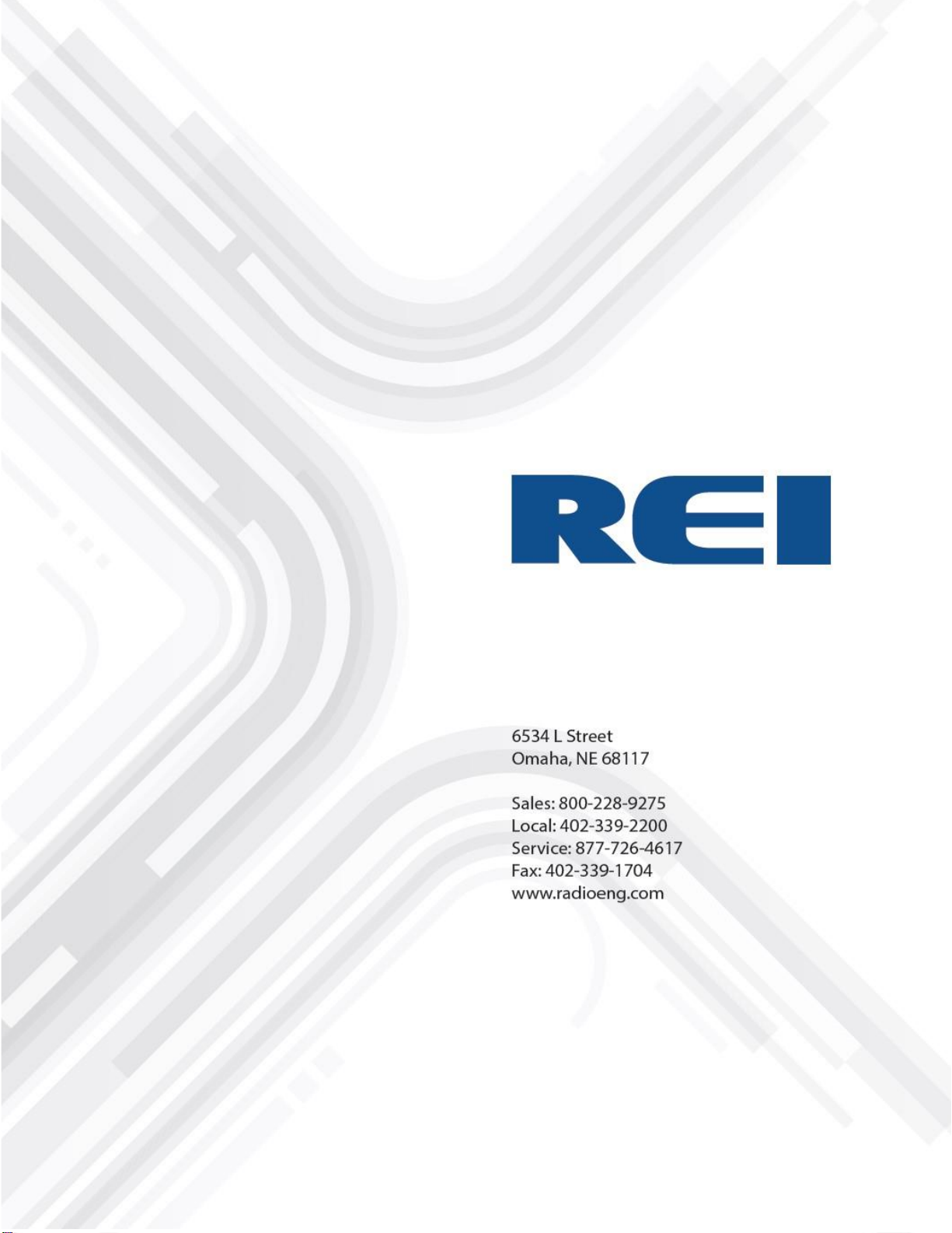
Check the firmware version by clicking the Info button and then the Versions button on the left column of the
window.
The firmware version needs to be at least T2019092601. The current firmware version can be located at
http://radioeng.info. Update the firmware by using a prepared USB drive. An alternate method of upgrading the
firmware is via the web: UI/ Maintenance/Firmware and verify the upgrade.
HD5 System Maintenance Check 6
HD5 System Maintenance Check Radio Engineering Industries, Inc. | 6534 L Street | Omaha, NE 68117
© 2020 Radio Engineering Industries, Inc. 800.228.9275 | p: 402.339.2200 | f: 402.339.1704 | radioeng.com
Checking Firmware Version
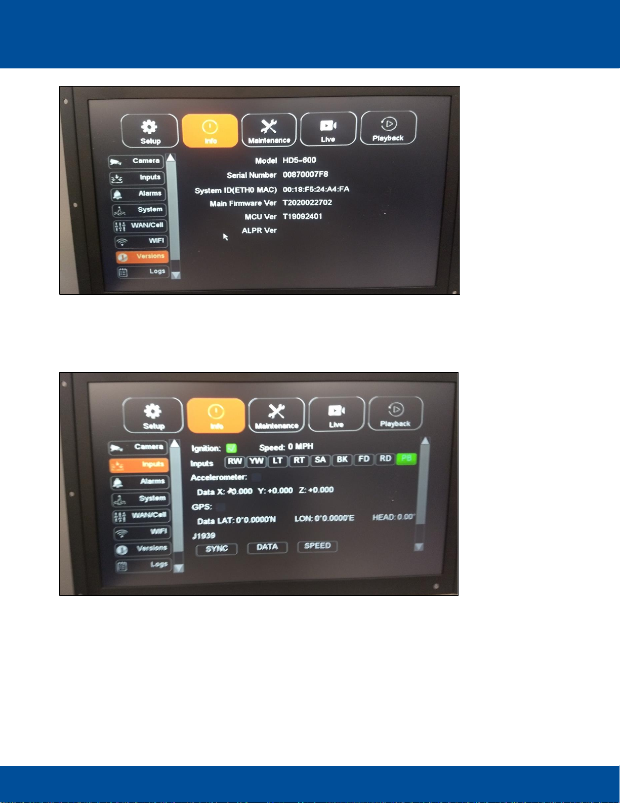
The Event Marker/Panic Button illuminates when the DVR is recording. It can be verified that when the Panic
button is pressed, it will be indicated as PB on the Info/Inputs field as depicted below.
Panic Button Selection Indicated on Inputs View
It is recommended that HDD storage is formatted at least annually. Formatting is performed by selecting
Maintenance/Storage/Format/Clear HDD. If DVR usage is heavy, HDD formatting should occur more
frequently.

HD5 System Maintenance Check 7
HD5 System Maintenance Check Radio Engineering Industries, Inc. | 6534 L Street | Omaha, NE 68117
© 2020 Radio Engineering Industries, Inc. 800.228.9275 | p: 402.339.2200 | f: 402.339.1704 | radioeng.com
Warning: All video data will be lost during formatting.
Selections made to Format/Clear HDD
After the drive is formatted, check if the following indicators are illuminated on the front of the DVR:
On:
PWR
REC
Off:
FLT
ALM
VLOSS
Inputs have three different types: School Bus, Transit, and Custom. The inputs to test for School Bus
are as follows:
RW: Red Warning
YW: Yellow Warning
LT: Left Turn
RT: Right Turn
SA: Stop Arm
BK: Brakes
FD: Front Door
RD: Rear Door

HD5 System Maintenance Check 8
HD5 System Maintenance Check Radio Engineering Industries, Inc. | 6534 L Street | Omaha, NE 68117
© 2020 Radio Engineering Industries, Inc. 800.228.9275 | p: 402.339.2200 | f: 402.339.1704 | radioeng.com
Verify the Accelerometer is working by checking if the X:, Y:, and Z: Coordinates are visible. An
illuminated green light in the check box next to the Accelerometer indicates a good connection.
Verify if the GPS is working by checking if the LON: and LAT: data indicators are visible. An illuminated
green light in the check box next to GPS indicates a good connection.
Speed settings are made using the Speed Source drop-down menu on Setup>Speed window. The GPS
and J1939 selections are the types of speed sources used by the DVR.
3Laptop Setup when Using a Web User Interface
To configure the network adapter:
Go to the Control Panel and in the upper right corner of the panel, set the View by: field to Small Icons.
Set View By: Field to Small Icons
Go to Network and Sharing Center.
Network and Sharing Center Window
Change the adapter settings. Reset the ethernet cord to verify target adapter.

HD5 System Maintenance Check 9
HD5 System Maintenance Check Radio Engineering Industries, Inc. | 6534 L Street | Omaha, NE 68117
© 2020 Radio Engineering Industries, Inc. 800.228.9275 | p: 402.339.2200 | f: 402.339.1704 | radioeng.com
Right click adapter and select Properties.
Selecting Properties
Select Internet Protocol Version 4 (TCP/IPv4) and select properties.
Adapter Configuration Settings
Configure adapter with settings as depicted above. Click OK to finalize.
Connect ethernet cable to front port.

HD5 System Maintenance Check 10
HD5 System Maintenance Check Radio Engineering Industries, Inc. | 6534 L Street | Omaha, NE 68117
© 2020 Radio Engineering Industries, Inc. 800.228.9275 | p: 402.339.2200 | f: 402.339.1704 | radioeng.com
4Conduct Ping Test to Verify Connectivity
Open the command prompt.
Searching for and Opening the Command Prompt
Enter “ping 192.168.200.200” and press enter.
Tabla de contenidos
Otros manuales de DVR de REI


