Regulus KPC1-BP Manual de usuario

Installation and Operation Manual
for a Solar System
with KPC1-BP Collectors
EN
v. 1.3

│2
CONTENTS
General Installation and Operation Instructions ............................................................................... 3
Collector Technical Data .......………………………………….………….............................................… 4
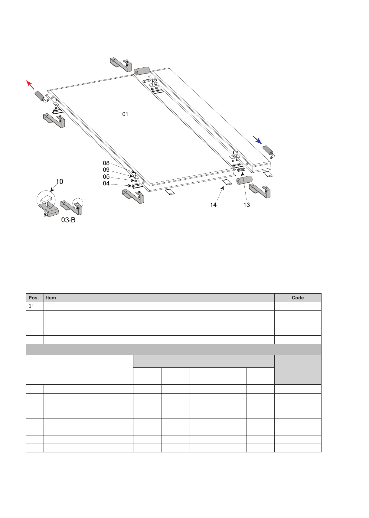
1 Delivery of Mounting System ..……………………..…………………..………................................... 5
2 Sloping Roof Mount ...………………………………...........………………...……................................ 6
2.1 Overview ...…………………....……………………………………………................................. 6
2.2 Roof anchor installation for sloping roofs ......…………………………................................... 7
2.2.1 Installation with roof anchors and auxiliary boards ..…………….......................... 7
2.2.2 Installation with roof anchors and rafters ………………………............................. 8
2.2.3 Installation with roof anchors for slate, shingle or metal roofs ….......................... 9
2.2.4 Installation with bolts for fixing rails onto a roof ................................................... 10
2.3 Installing rails onto roof anchors .......……………………………………................................. 10
2.4 Collector mounting .……………………………………………………….................................. 11
3 Connection Pipe Passage through a Roof ………………………………….…................................. 12
4 Flat Roof Mount .................……………………………………………………..…................................. 13
4.1 Overview ……………………………………….……………………………............................... 13
4.2 Flat roof support mounting ...............…………………………………….................................. 14
5 Hydraulic Connection ...……………………………………………………...……................................ 18
5.1 Collector connecting .......……………….....….…………………………………....................... 18
5.2 Collector interconnecting …………………......…………………………….............................. 18
6 Temperature Probe Positioning …………………………………………….……................................ 19
7 Pump Station ...........…………………………………………………………...……............................... 20
8 Expansion Vessel Sizing and Working Pressure Calculation ...........………............................... 21
8.1 Expansion vessel sizing .......……………………………………………...............................… 21
8.2 Calculation of a system working pressure .…………………………...................................… 21
8.3 Calculation of an expansion vessel preset pressure .....……………................................…. 21
8.4 Examples of calculating working pressure and expansion vessel pressure ....................…. 21
8.4.1 Example of calculating system working pressure ...................................……. 21
8.4.2 Example of calculating expansion vessel pressure .............................………. 21
9 Installation of Air Release Valves ..……………………………………………...............................…. 22
10 System Filling, Flushing, Leak Test and Air Bleeding ..........................….................................... 23
10.1 Filling ……………………………………………...............………...............................………. 23
10.2 Flushing ………………………………….......………………………...........................………. 23
10.3 Air bleeding ……………………….................…………………….....................................…. 24
10.4 Leak test .............................…………………………………………..............................……. 24
11 Commissioning …………………………..........……………………………......................................…. 24
12 Operation, Checks and Maintenance ...........……………………............…………......................…. 24

3 │
GENERAL INSTALLATION AND OPERATION INSTRUCTIONS
Collector description
REGULUS Flat Plate Solar Collectors are designed for solar domestic hot water heating, backup and pool
heating. Solar radiation penetrates the glass and is intercepted by an efficient absorption layer applied on
a serpentine-shaped copper absorber. The heat is then transferred into heat carrier fluid. The absorber is sealed
in a compact frame with high quality thermal insulation. The collectors are designed for all year round operation,
that’s why they work in a separate primary circuit filled with antifreeze heat carrier. The collectors are not
intended for direct water heating.
Transport and handling
Collectors shall be transported in their original packing, in upright position (standing on their shorter side) or lying
horizontal with glass upwards, stack of max. 10 pieces of KPC1-BP.
Installation
The installation must be done by a skilled worker or a specialized company. During installation and before
commissioning, it is necessary to cover collectors in order to avoid overheating and possible burns caused by
the hot surfaces. If the collector shall be set on a roof, appropriate safety rules must be observed.
Collector placing
The glass absorption surface should be orientated to South, with deviations not over 45° (Southwest or
Southeast). For all year round operation the right inclination angle is 40° - 50°, for summer operation smaller
inclination is better (30°). The collector can be positioned also vertically (inclination angle of 90°, e.g. onto an
outer wall), that is the best for winter operation. The inclination angle must not be less than 20°.
It is recommended to install solar collectors close to the roof ridge due to a snow load in the winter.
Lightning protection
Lightning protection is obligatory for solar systems. When installed on a roof, collectors must be wired to lightning
protection equipment. Local standards shall be observed.

│4
Collector Technical Data
Model KPC1-BP
Dimensions W x L x H [mm] 1000 x 2000 x 96
Collector surface [m2]2
Connection dimensions 4 × Ø 22 mm Cu
Absorber nickel-plated copper / tube-grid type
Absorber surface black chrome
Insulation thickness [mm] 40
Max. working pressure [bar] 6
Fluid volume [l] 2
Weight [kg] 37
Glass [mm] 4 - solar prismatic
Recommended flow rate [l/h] 60 - 120
Pressure drop [Pa]
flow rate [l/h]
Pressure drop [Pa]

5 │
Mounting kits for fixing and connecting KPC1-BP solar collectors Code
Connection kit for a KPC collector array
(3/4“ M inlet and 3/4“ M outlet with a pocket for solar temperature sensor)
7710
Roof fixing kit for one KPC 1 collector
*for 4 anchors or 2 struts+1 wind brace
7720
Roof fixing and interconnecting kit for two KPC 1 collectors
*for 4 anchors or 2 struts+1 wind brace
7712
Roof fixing and interconnecting kit for three KPC 1 collectors
*for 6 anchors or 3 struts+1 wind brace
7714
Roof fixing and interconnecting kit for four KPC 1 collectors
*for 8 anchors or 4 struts+1 wind brace
7716
Roof fixing and interconnecting kit for five KPC 1 collectors
*for 10 anchors or 5 struts+1 wind brace
7718
* Roof fixing and interconnecting kits are necessary to create a hydraulically connected collector array fixed to
2 mounting rails. The kits contain interconnecting fittings with insulation, two mounting rails, fastening material
for mounting collectors onto the rails. They do not involve any roof anchors, struts, wind braces. These shall
be selected from the following chart by the roof type and roofing material.
Roof anchors for different types of roofing Code
Aluminum anchor for slate or shingle roofs 6920
Aluminum anchor for pantiles - adjustable height 7013
Anchor for pantiles - hot-dip galvanized steel 7929
Aluminum anchor for pantiles - rafter mounted 6932
Stainless-steel anchor for pantiles 6857
Bolt for fixing rails onto a roof 7320
1 Delivery of Mounting System
Handle with care, transport damage should be claimed immediately.
Struts and braces for flat roof installations Code
Triangular strut for support structures - flat roof 6859
Wind brace 6860

│6
2 Sloping Roof Mount
2.1 Overview
Pic. 1: Collector array and roof anchors
01
14 13
08
09
05
04
10
03-B
Pos. Item Code
01 Flat plate collector 7610
03-B
10 Roof anchor with M8 bolt/special head for rails
6857 or other,
depending on
roofing type
Interconnecting pipes
Fixing and interconnecting sets
No. of collectors (kit code)
Item code
1
(7720)
2
(7712)
3
(7714)
4
(7716)
5
(7718)
04 H profile base rail, aluminum, 2 pieces 1.08m 2.14 m 3.205 m 4.28 m 5.35m 6949
05 M8 nut for the base rail 4 pcs 8 pcs 12 pcs 16 pcs 20 pcs 6925
08 M8x18 stainless-steel bolt (allen head) 4 pcs 8 pcs 12 pcs 16 pcs 20 pcs 7259
09 Retaining side bracket 4 pcs 8 pcs 12 pcs 16 pcs 20 pcs 7725
14 Retaining bracket for collector bottom 2 pcs 4 pcs 6 pcs 8 pcs 10 pcs 7709
13 Threaded fittings - 2 pcs 4 pcs 6 pcs 8 pcs 7629
Insulation 35 mm diam., 19 mm thick 0.5 m 0.75 m 1 m 1.5 m 2 m 7188
Insulation tape 0.8 m 1 m 1.5 m 2 m 2.5 m 7227

7 │
2.2 Roof anchor installation for sloping roofs
Pay attention to situations when battens are thicker than the auxiliary board (30 mm). Then the auxiliary board
shall be mounted on an underlay so that its total thickness equals to that of the battens (see pic.).
When installing anchors on a rafter, use an underlay as well depending on how thick the battens and counter
battens are, so that the installed anchors do not hinder proper seating of tiles.
40
30
10
30
30
auxiliary board
battens
counter batten
rafter
waterproofing membrane
underlay
Pic. 2: Underlay to match thick battens
Pic. 3: Stainless-steel roof anchor Hot-dipped steel roof anchor Aluminum roof anchor
140−160
290
99
40
79−99
65.5
Ø 6
125
80
65
40
300
100
35
Ø 6
120
80
90
35
300
45
40
Ø 6
2.2.1 Installation with roof anchors and auxiliary boards
• for tile roofs, 3 cm thick additional auxiliary boards shall be mounted to the bottom side of the roof. Then hook
the anchors onto the board and fix with a bolt.

│8
• screw the auxiliary boards so high that the roof anchor does not hinder placing the roof tile with the right
overlap
• hang the roof anchor onto the auxiliary board in a place where it will not hinder the right tile positioning, and
screw the roof anchor with stainless-steel bolts
• for two or more collectors place the anchors about the presumed middle of the collector (distance a)
2.2.2 Installation with roof anchors and rafters
For tiled roofs, rafter anchors can be used. The anchor with a board is made of aluminum and enables horizontal
shift of the anchor along the fixing board.
a
Pic. 5: Fixing an auxiliary board and roof anchors
150
120
136−156
65.5
40
Ø 9
54
56
180
Pic. 6: Roof anchors for rafters
• remove tiles in a line about as long as the auxiliary board. Usually it is sufficient to shift the tiles upwards.
Pic. 4: Remove roof tiles to fix the board
room for an auxiliary board
counter batten
rafter
roof battens

9 │
• remove roof tiles where the anchors shall be mounted
Pic. 7: Opening the room for anchor installation
• screw a roof anchor to a rafter and shift it
in the groove horizontally so that it does not
hinder the right tile positioning
• for 2 or more collectors place the anchors
always about their presumed middles
2.2.3 Installation with roof anchors for slate, shingle or metal roofs
• Simply lay the anchor onto the roof tiles in a place
where the roof is supported with a strong roofing element
(a beam or another support) and fix it with stainless-steel
bolts. Cover the anchors with sheet metal to prevent water
leakage or use another suitable method recommended by
the roofing manufacturer.
Ø 6
6
228 78−98
Pic. 9: A roof anchor for slate, shingle or metal roof
• cut the counter batten used for fixing the waterproofing membrane and if necessary, use an underlay depending
on the desired anchor height
Pic. 8: A place for mounting a roof anchor on a rafter - detail
counter batten
rafter
roof battens
room for anchor mount
counter batten
rafter
roof
battens
waterproofing membrane

│10
2.3 Mounting rails on roof anchors
• have ready two rails in the length required for the number and type of collectors to be installed. Align the
travelling screw head (10) with the horizontal rail and shift the rail onto it, or shift the screws into the rail and fix
to the anchors. Use serrated lock washers to fix the nuts.
Pic. 10: Fixing the rail onto the roof anchors
2.2.4 Installation with bolts for fixing rails onto a roof
This method of installation
is preferably used for roofs
of bitumen corrugated
sheets like Gutta or Ondu-
line etc., or for corrugated
eternit or metal sheets. The
bolt shall be screwed into
a rafter or another massive
wooden roof element using
spanner No. 8. Pre-drilling 6 mm diam. holes is recommended. Holes should be always drilled in the crest of
the roofing wave, not in its valley to avoid leakage. After screwing the bolt in, put on the rubber seal and using
a washer and nut, seal the drilled hole. Then mount the U-shaped bracket on the bolt, between two nuts with
a serrated washer. Then M8 bolt with floating head (for rails) shall be mounted into the other end of the bracket.
First insert the floating head into the groove of the rail, and then tighten the bolt together with the rail to the
U-shaped bracket using a nut and a serrated washer.
100
ø 9
80
140
40
40
roof anchor
top / bottom rail
M8 bolt with
travelling head
Tabla de contenidos
Otros manuales de Panel solar de Regulus

Regulus
Regulus Ashburn KPI1 Manual de usuario

Regulus
Regulus KPS1 Manual de usuario

Regulus
Regulus LYRA 1000 VVS Manual de usuario

Regulus
Regulus KPS11 Manual de usuario

Regulus
Regulus VEGA 390 Manual de usuario

Regulus
Regulus KPG1H-ALC Manual de usuario

Regulus
Regulus KPG1-ALC Manual de usuario

Regulus
Regulus KPC1 BP Manual de usuario


