Redexim Verti-Drain 7621 Manual del producto

NOTE:
IN ORDER TO ENSURE THE SAFE USE AND TO ACHIEVE THE
BEST PERFORMANCE, IT IS ESSENTIAL THAT THIS
OPERATORS MANUAL IS CAREFULLY READ BEFORE THE
VERTI-DRAIN® IS USED.
1735 English 911.120.040
Operator and
Parts manual
Verti-Drain®
Model 7621
Serial number:
Translation of the original operating instructions
Kwekerijweg 8
3709JA Zeist
The Netherlands
T: (31)306933227
F: (31)306933228
www.redexim.com

2
FOREWORD
Congratulations on your purchase of the Verti-Drain®. To ensure the long and safe use of this
Verti-Drain®, it is of the utmost importance for all those who will be using it to read and
understand this user manual. Without full knowledge of the content, operation of this
machine is not safe.
The Verti-Drain® is not an independently operating machine. The user is responsible for
using the appropriate tractor. The user must also check the tractor/Verti-Drain® combination
for safety aspects such as the noise level, adequate user instructions, and possible risk
factors.
The Verti-Drain® is solely intended for use on lawns and other areas where grass could grow.
On the next page you will first find the general safety instructions. Every user must know and
be able to apply them. After this, a registration card is included. This card should be returned
in order to be able to handle any future claims.
This user manual offers many instructions numbered in sequence. This sequence should be
observed. An asterisk * indicates a safety instruction. An @ indicates a tip and/or note.
All information and technical specifications provided at the moment that this
document is published are the most recent ones. Design specifications may be
changed without prior notice.
This document is a translation of the original operating instructions.
Upon request, the original operating instructions are available in Dutch.
WARRANTY CONDITIONS
THIS VERTI-DRAIN® IS DELIVERED WITH A WARRANTY AGAINST DEFECTS IN
MATERIALS.
THIS WARRANTY IS VALID FOR A PERIOD OF 12 MONTHS FROM THE PURCHASING
DATE.
VERTI-DRAIN® WARRANTIES ARE SUBJECT TO THE “GENERAL CONDITIONS FOR
SUPPLY OF PLANT AND MACHINERY FOR EXPORT, NUMBER 188”, WHICH ARE
PUBLISHED UNDER THE AUSPICES OF THE UNITED NATIONS ECONOMIC
COMMISSION FOR EUROPE.
REGISTRATION CARD
For your own information, please complete the table below:
Serial number machine
Dealer name
Date of purchase
Remarks
3
! SAFETY INSTRUCTIONS !
Fig. 1
The design of the Verti-Drain® allows for safe use.
However, this is only possible if the user
completely follows the safety instructions given in
this manual.
Read and understand (Fig. 1) the manual before
beginning to use the Verti-Drain®.
If the machine is not used as described in the
manual, injury and/or damage to the Verti-Drain®
may result.
(1) The Verti-Drain® is solely intended for the treatment of lawns or other areas
where grass should grow.
Any other use is considered to be incorrect use. The manufacturer accepts no
liability whatsoever with regard to damage resulting from such incorrect use; all
resulting risks are the responsibility of the user.
Correct use also includes following the manufacturer’s usage, maintenance and
repair instructions.
Before using the Verti-Drain®, inspect the area to be treated. Remove any loose
obstacles and avoid irregularities.
(2) The Verti-Drain® was constructed according to the latest technological
knowledge and is safe to use.
Improper use, maintenance or repair of the machine may result in injury to both
the user and others. This should be avoided!
Always use the Verti-Drain® in combination with the proper tractor as described in the
technical data.
(3) All persons whom the owner assigns to operate, maintain or repair the Verti-
Drain® must read and have completely understood the operating manual and in
particular the section Safety Instructions.
The user is responsible for a safe tractor/ Verti Drain® combination. This
entire unit must be tested in terms of noise, safety, and ease-of-use. In
addition, user’s instructions must be prepared.
(4) Before using the Verti-Drain®, the user is obliged to inspect it in terms of visible
damage and defects. Any changes in the Verti-Drain® (including its functioning)
that may affect its safety must be corrected immediately. For reasons of safety, it
is in principle forbidden to make changes in or additions to the Verti-Drain® (with
the exception of those approved by the manufacturer).
If any modifications have been made to the Verti-Drain®, the present CE
certificate becomes null and void and the person who made the modifications
should himself make sure a new CE certificate is granted.
4
Before each use, inspect the Verti-Drain® for loose bolts/nuts/parts.
If present, inspect the hydraulic hoses regularly and replace these if they are
damaged or show signs of wear. The replacement hoses must meet the
manufacturer’s technical specifications.
Always relieve the pressure from the hydraulic installation, if present, before
carrying out any work on it.
NEVER use de Verti-Drain® if its protective covers and safety decals are
missing.
NEVER crawl underneath the Verti-Drain®.
If you need to access the bottom, tilt the Verti-Drain®.
NEVER step off the tractor while the engine is still running.
When carrying out maintenance, adjustments or repairs, make sure the Verti-
Drain® is blocked from sagging/moving/sliding.
Before carrying out any maintenance, adjustments or repairs, always switch off the
tractor engine first, remove the tractor key from the ignition, and disconnect the
PTO (Fig. 2).
Fig. 2
When carrying out any maintenance or repairs, make sure to use original Verti-
Drain® parts only. This will ensure continued safety of the machine and its user.
Only authorised technical personnel may carry out adjustments and repair work
to the Verti-Drain®.
Keep an overview of repairs.
(5) In addition to the instructions in this user manual, the generally applicable
regulations with respect to safety and working conditions must be followed.
For use on public roads the relevant guidelines of the Highway Code also apply.
Transporting persons is not permitted!
Do not use the Verti-Drain® when it is dark, during heavy rain/ storms, or on slopes with
a gradient greater than 20 degrees.
(6) Before starting to work, all persons who will operate the Verti-Drain® must be
familiar with all its functions and controls.

5
Connect the Verti-Drain® to the vehicle that will pull it exactly according to the
instructions (Danger of injury!)
Before driving off, make sure you have a clear view both nearby and far away.
On both sides of the Verti-Drain®, decals (Fig. 3,4,5) are applied to the sideboard
(Fig. 6) showing these warnings. Make sure these safety decals are always clearly
visible and legible. Replace them if they are damaged.
During operation, make sure there are NO persons in the danger area of the
Verti-Drain®, because they may be injured by moving parts. (Fig. 3)
Fig. 3
Fig. 4
Remain at least 4 metres away! (Fig. 4)
The back cover must always be closed and undamaged during operation of the
machine! (Fig. 5)
Be careful not to get pinched when opening the rear cover! (Fig. 6)
Fig. 5
Fig. 6
Be aware of the maximum lifting capacity of the towing vehicle.
Wear suitable clothing. Wear sturdy shoes with a steel tip, wear long trousers, do up
long hair and wear no loose clothing.

6
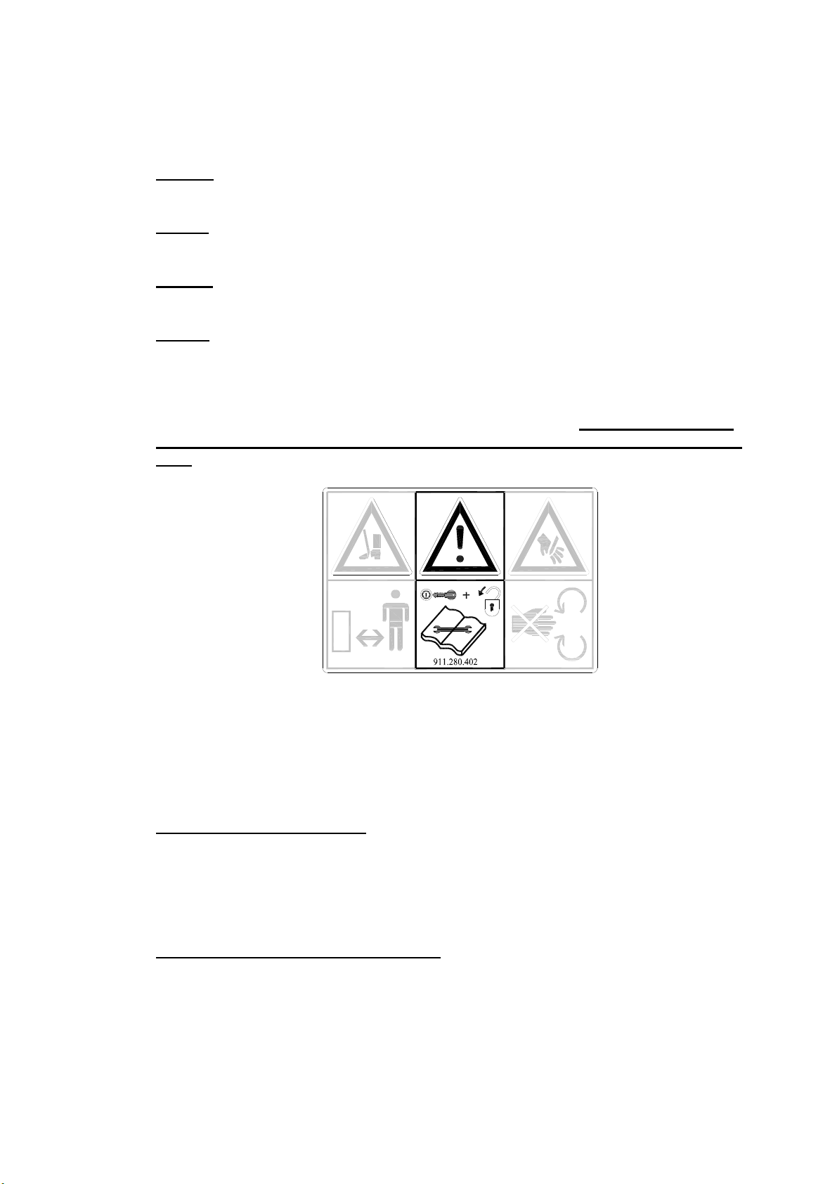
(7) Location of safety stickers. (Fig. 7)
Fig. 7
Used oil/grease is harmful to the environment; dispose of it according to locally
applicable regulations.

7
CONTENTS
Section Description Page
Foreword 2
Warranty conditions 2
Registration card 2
Safety instructions 3
1.0 Technical data 8
2.0 First installation, removing the machine from the pallet 9
3.0 The power take-off shaft 10
3.1 The length of the power take-off shaft 10
3.2 Use of the power take-off shaft 11
3.3 Slip coupling information and maintenance 11
4.0 Adjusting the operating depth 12
5.0 Pin angle adjustment 12
6.0 Driving speed 13
7.0 Start procedure 14
8.0 Operation of the Verti-Drain
®
15
9.0 Transportation of the Verti-Drain
®
15
10.0 Disconnecting the Verti-Drain
®
15
11.0 Troubleshooting 16
12.0 Maintenance 17
13.0 EU certificate 19
14.0 Technical information 20
14.1 Torque values 20
14.2 The crankshaft 21
14.2.1 Replacement of an oil catcher 21
14.2.2 Replacement of a crank throw / crank bearing 21
14.2.3 Releasing crankshaft tension 22
14.3 Aligning an element 22
15.0 Option, Turf hold-down kit 23
15.1 Option, pins 24
15.1.1 Solid pins 24
15.1.2 Hollow pins 25
Parts pages

8
1.0 TECHNICAL DATA
Model 7621
Operating width 2.10 m (83”)
Operating depth Up to 400 mm (16”)
Tractor speed measured at 500
rpm PTO-shaft speed
Hole separation 65 mm (2-1/2”)
Hole separation 130 mm (5”)
Hole separation 195 mm (7-1/2”)
Up to 0.75 km/hr (0.47 mph)
Up to 1.50 km/hr (0.93 mph)
Up to 2.25 km/hr (1.40 mph)
PTO-shaft speed: (max.) Up to 500 rpm
Weight 1565 kg (3450 lbs)
Hole separation between the pins 129 mm (5”) with 24 mm (1”) holes
65 mm (2.5”) with 12 mm (1/2”) holes
Hole separation in driving
direction
50 – 195 mm ( 2 - 7 1/2”)
Recommended tractor 55 HP with minimum lifting capacity of 2000 kg
(4408 lbs)
Double-acting external hydraulic connection.
Maximum capacity
Hole separation 65 mm (2-1/2”)
Hole separation 130 mm (5”)
Hole separation 165 mm (6-1/2”)
Up to 1575 m²/hr (16953 ft²/hr)
Up to 3150 m²/hr (33906 ft²/hr)
Up to 4725 m²/hr (50859 ft²/hr)
Shipping dimensions 2300 x 1100 x 1560 mm
(90,5” x 43.3” x 61.4”)
Maximum pin size Solid 24 x 400 mm (1”x 16”)
Hollow 32 x 300 mm (1-1/4”x 12”)
Slip coupling, gearbox Maximum 1100 Nm (9680 lb.inch.)
Three-point connection 3- point CAT 2
Gearbox oil 80W90 (6.5Ltr.)
Lubricant EP 2
Standard parts Set of solid pins 24/400 (0,95” x 16”)
Front and back roller.
3-speed gearbox.
Tool tube with tools.
Hydraulic adjustment of the operating depth.
PTO shaft.

9
Verti-Dra
7621
R
Verti-Drain
7621
Verti-Dra
7621
Detail A
Pin 3
PTO−cover
Hole 4
Lock Hole
Verti-Drain
7621
R
Fig. 8
2.0 FIRST INSTALLATION, REMOVING THE MACHINE FROM THE
PALLET
The machine is standing vertically on the pallet. To remove the pallet and lay the machine horizontally,
carry out the following steps (see fig. 8):
1. Open the rear cover
2. Fasten a cable to the lifting point
* Make sure that the cable/crane/lift can lift at least 2500 kg (5512 lbs)
3. Raise the machine, including the pallet, 50 mm from the ground.
4. Remove the pallet by sliding it over the bottom 3-point pins
* Do not crawl under the machine!!
5. Lower the machine slowly until the 3-point connection plates touch the ground.
6. Lower the machine further so it can run on the front roller
7. Continue to lower the machine until it rests on the front and rear rollers.
8. Install the included PTO cover.
9. Attach the machine to a tractor.
* Use the correct tractor. See the specifications.
10. Connect the hydraulic hoses to the tractor.
11. Raise the machine off the ground.
12. Open the valve on the right-front side of the machine (Detail A) by turning it anti-clockwise
(with the included key) to purge the hydraulic operating-depth adjustment system of air.
13. Activate the hydraulic output of the tractor, and carefully lower the roller to remove the air from
the system.
14. Close the valve of the right-front side of the machine (Detail A) by turning it clockwise (with the
included key).
When the system still contains air repeat point 13 and 14 to remove this.
The system is now free of air and ready for use.
15. Remove the locking pins for the rear roller. Put pins 3 in hole 4.
16. Lower the machine to the ground, and turn the top rod to adjust the angle of the machine to 90
degrees.
@ this angle of 90 degrees is very important for the correct operation of the machine.
17. Set the tractor’s stabiliser to 100 mm lateral movement.
18. Mount the pins. Grease the end that will be inserted.
19. Length of the PTO shaft, see 3.1.
20. When machine is taken of the pallet, remove the upper plug of the gearbox and replace it with
the supplied breather.
10
3.0 The PTO shaft
The PTO shaft is a very important part. It provides the driving force from the tractor and – if
installed, used, and maintained correctly – ensures safe use of the machine. The PTO shaft
has its own CE certificate. Make sure to read the PTO shaft manual. It is located on the PTO
shaft itself.
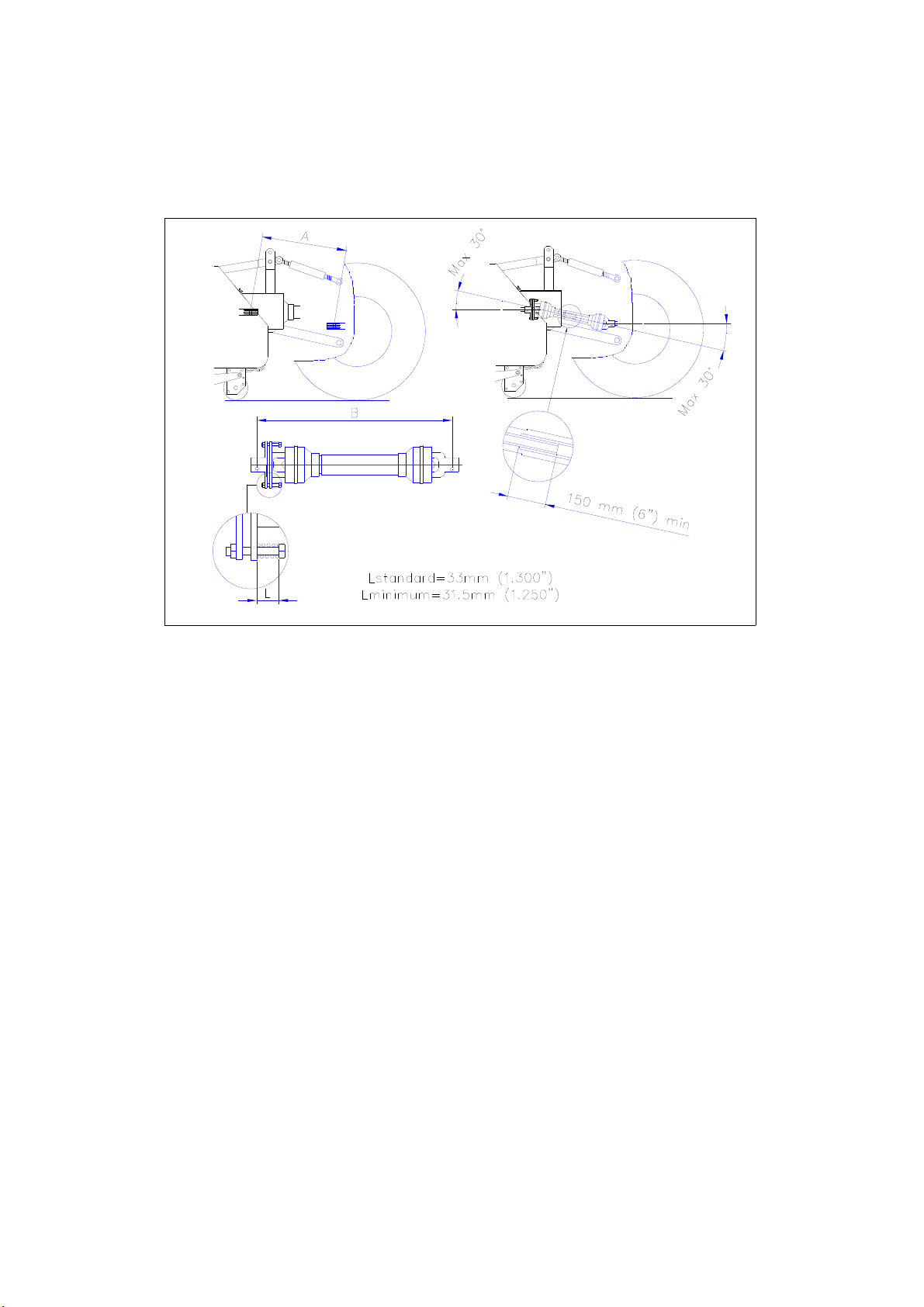
Fig. 10
3.1 LENGTH OF THE PTO SHAFT
The length of the PTO shaft is very important. If it is too long, it may damage the drive of the
tractor and/or the Verti-Drain®. If the overlapping length of the sleeves is, at any time, shorter
than 150 mm, the PTO shaft may be damaged.
*The length will vary when the machine is raised or if another tractor is used.
To make sure the length of the PTO shaft is correct, after purchase or when using another
tractor, carry out the following steps: (see Fig.10)
1. Measure the distance between the PTO connection of the tractor and that of the Verti-
Drain, from groove to groove, when the machine is at the correct angle on the ground
and attached to the tractor.
2. Measure the distance B of the PTO at its shortest position, from locking pin to locking
bolt.
3. Split the PTO in two and remove the protective cover from both ends.
4. Both the sleeve ends and the cover ends have to be shortened: (B-A) + 75 mm (3”).
5. Debur, grease, and assemble all parts.
6. Attach the PTO with the slip-connection side facing the Verti-Drain.
*The torque of the locking bolt must be 80 Nm (9700 lb.in.) and must be checked
every 40 hours.
7. Attach the other end of the PTO to the tractor.
8. Check the overlap of the sleeves.
*Never use the machine if the protective cover of the PTO is damaged.
Replace it first.
Tabla de contenidos
Otros manuales de Caña del timón de Redexim


