Really Right Stuff FH-7240 Manual de usuario

FH-7240
CINEMA FLUID HEAD
720 S 850 E Lehi, UT 84043
1-385-248-0777 | 1-888-777-5557
www.ReallyRightStuff.com
© 1990-2019 Really Right Stuff, LLC. All rights reserved.

IN THE BOX
(1) FH-7240 FLUID HEAD
(1) BENG-5 MOUNTING PLATE 5” WITH SPRING-LOADED SAFETY STOPS
(1) TA-LBLP LOW PROFILE LEVELING BASE LOCK KNOB
(2) B113 CUSTOM 3/8-16 MOUNTING SCREWS
(2) B114 CUSTOM 1/4-20 MOUNTING SCREWS
(1) 5/32 HEX KEY
(1) FH-7240 USER’S GUIDE
(1) CR1632 BATTERY
(1) CUSTOM CARRY CASE

2
www.reallyrightstuff.com
1
LENGTH 5 in (127 mm)
WIDTH 6.45 in (163.9 mm)
HEIGHT
(CLAMP TO MOUNTING STUD TIP) 9.85 in (250.1 mm)
HEIGHT
(100MM BALL BASE CENTER
TO PLATFORM)
6.86 in (174.2 mm)
HEIGHT
(TILT AXIS TO PLATFORM) 2.8 in (71.2 mm)
CONTROL ARM LENGTH
(COLLAPSED) 13.63 in (346.1 mm)
CONTROL ARM LENGTH
(EXTENDED) 22.44 in (569.9 mm)
CONTROL ARM
CARBON TUBE DIAMETER .964 in (24.5 mm)
WEIGHT
(WITHOUT MOUNTING PLATE,
CONTROL HANDLE, AND LOCK KNOB)
7.49 lbs (3398 g)
WEIGHT
(WITH EVERYTHING INCLUDED) 8.47 lbs (3844 g)
MEASUREMENTS
Introducing the Really Right Stuff FH-7240. Three
years in the making, this video fluid head is a culmi-
nation of countless hours of research and testing.
The FH-7240 combines class-leading performance,
high quality, precision, ergonomics, fast setup, and
smooth operation seamlessly into one product.

4
www.reallyrightstuff.com
3
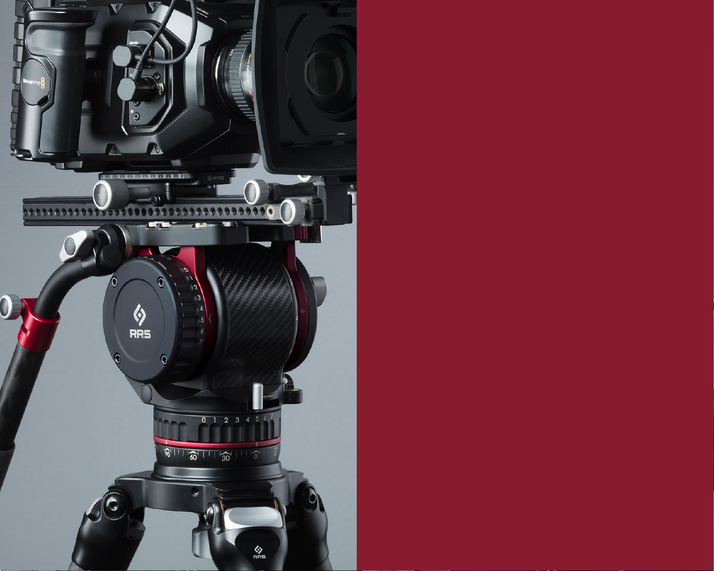
INDEXABLE HANDLE — An Arri-compatible Rosette locking design allows for
fine adjustment and superior load capacity. Loosening the T-Handle Lock Knob
allows you to adjust the position and rotation of your handle precisely where
you want it, then lock it down by tightening the knob. No tools are required to
swap the handle to the other side. When the Multi-Lock Swivel assembly is fully
disconnected from the head, pull out on the T-Handle Lock Knob to disengage
the screw shaft from the alignment groove in the bent tube. This allows the tube
to be flipped over to the other side of the Multi-Lock Swivel.
TELESCOPING HANDLE — The telescoping carbon fiber handle with grip allows
for length adjustment of 13 to 21 inches. The diameter of the tube is 0.964 inches
or 24.5 mm. Use caution when clamping accessories on the carbon fiber tube to
avoid pinching and crushing the tube. Use band-style clamps where possible to
evenly distribute pressure around the tube.
TILT DAMPING ADJUSTMENT WHEEL — Rotate wheel to adjust tilt damping.
Numbers align with index mark in multiple discrete positions to deliver 7 different
levels of damping. Damping ranges from Off (0) to High (7). There are no
intermediate settings between numbers.
LEVELING BASE — Loosen the Leveling Base Knob to allow for fine leveling
adjustment up to 15°. Tightening the knob locks the fluid head’s position with
the stability of a 100mm bowl. Note that continuing to rotate the knob in the
loosening direction will remove it and allow the fluid head to be removed from the
tripod. Also, ensure there is sufficient thread engagement for the load before use.
FOLDING COUNTERBALANCE ADJUSTMENT CRANK ARM — Unfold the crank
arm by first pressing the stainless steel unlock button located on one side, then
flipping the crank arm into the locked position. Once unfolded, rotate the Crank
Arm clockwise to increase the counterbalance restoring torque. Decrease the
counterbalance restoring toque by rotating the Crank Arm in the counter-clockwise
direction.
PAN DAMPING ADJUSTMENT WHEEL — Similar to the Tilt-Damping Adjustment
Wheel, rotate the Pan Damping Adjustment Wheel to change the level of fluid
damping. There are no intermediate settings between numbers.
TILT LOCK LEVER — Rotate the Tilt Lock Lever toward the direction of the Lock
symbol near the arrow to lock the fluid head’s tilt axis at any position. Loosen the
tilt axis by rotating the lever the opposite direction. Note that the lever is captive
and is factory set with the proper amount of clamping force. User adjustment
is not required.
ALLEN KEY STORAGE —Store the provided Allen Key (used to attach and detach
plates from the camera) within the Quick Release Clamp. Magnets hold the Allen
Key in place while not in use.
QUICK-RELEASE CLAMP — Lever-release clamp* accepts all Really Right Stuff-
compatible plates and rails.
2
3
4
5
6
7
8
FEATURES
REAR VIEW
1. Indexable handle
2. Telescoping handle
3. Tilt Damping Adjustment Wheel
4. Leveling Base
5. Folding Counterbalance Adjustment Crank Arm
6. Pan Damping Adjustment Wheel
7. Tilt Lock Lever
8. Allen Key Storage
9. Quick-Release Clamp
10. Clamp Lever
11. Top-Load Release Button
12. Spirit Level and Light
13. Precision Laser Markings
14. Pan Lock Lever
1
1
2
3
4
5
6
7
8
9
*Other brand plates listed as Arca-Swiss compatible may also fit but only mounting plates made by RRS are guaranteed to our
50 lbs. no-slip rating. Oversized dovetail plates can permanently damage the clamp if forced to close. Contact RRS Customer
Service prior to using a non-RRS plate to verify compatibility and use.
9

6
www.reallyrightstuff.com
5
10
11
12
13
14
CLAMP LEVER — The clamp lever incorporates a Safety Latch. To unlock the
clamp for sliding, first push the Safety Latch forward, then swing the lever open.
The clamp is fully closed and locked on the quick-release plate when the lever is
firmly closed back to its original position and the Safety Latch has clicked back
into place. For ultimate security, lock the Safety Latch into place using a cotter
pin, cable lock, or small screw (not provided).
TOP-LOAD RELEASE BUTTON —To fully open the clamp from the sliding position
simply press the red button and pull the mounting plate up until you hear a click.
Doing this allows the plate to be removed from the fluid head from the top rather
than requiring it to be slid out.
To load the plate and camera, first ensure the Clamp Lock Lever is in the open
position and the red Top-Load Release Button is depressed. This cocks the jaw
back to the fully open position and allows the spring-loaded silver catch to pop
up into position. Top-load the camera plate by placing the dovetail furthest from
the Clamp Lock Lever into the clamp first, then tilting the camera plate down to
depress the silver catch. This closes the jaw to the sliding position, enabling the
operator to balance the camera before closing the Clamp Lock Lever to lock the
plate in position. See page 7 for more details.
SPIRIT LEVEL AND LIGHT — Use the spirit level to ensure the pan axis is level with
the horizon. Center the bubble in the circle marked on the top of the spirit level.
For best results, look at the level top-down rather than off-axis. For use in the
dark, press the silver button above the level to turn on a red light that illuminates
the level. This light will automatically turn off after approximately 15 seconds. The
battery is a user-replaceable CR1632, located behind the round cap adjacent
to the level.
PRECISION LASER MARKINGS — Use precision laser markings on the pan and tilt
axes to produce repeatable positioning of the fluid head. Axes are laser engraved
in 5° increments; numbers and chevrons are lasered in 30° increments.
PAN LOCK LEVER — Push the Pan Lock Lever toward the direction of the lock
symbol near the arrow to lock the head’s pan axis in any position. Partially
engaging the pan lock is not recommended. Push lever until the hard stop is felt
in both the locked and unlocked positions. Note that the pan and tilt lock levers
are designed with an ergonomic pinch-to-unlock feature. When both pan and
tilt are locked, simply pinch together on both levers to quickly unlock the head
for movement.
FEATURES CONTINUED
FRONT VIEW
1. Indexable handle
2. Telescoping handle
3. Tilt Damping Adjustment Wheel
4. Leveling Base
5. Folding Counterbalance Adjustment Crank Arm
6. Pan Damping Adjustment Wheel
7. Tilt Lock Lever
8. Allen Key Storage
9. Quick-Release Clamp
10. Clamp Lever
11. Top-Load Release Button
12. Spirit Level and Light
13. Precision Laser Markings
14. Pan Lock Lever
10
11
12
13
14
8
1
2
9

8
www.reallyrightstuff.com
7
ATTACHING THE
QUICK-RELEASE PLATE
Following these steps, make sure to engage the lock lever by
closing it again (opposite of step 1) to lock the camera in place.
STEP 1
STEP 2
STEP 3
RELEASE THE LOCK LEVER
DEPRESS THE RED TOP-LOAD RELEASE BUTTON
PLACE THE DOVETAIL ON THE SIDE OPPOSITE OF THE LOCK LEVER FIRST, THEN PRESS DOWN.
The BENG-8 and Arri-Dvtl-300 mounting plates are available as optional
accessories during purchase. Please call us or visit our website to purchase
the specific plate for your camera and application.
SUGGESTED ACCESSORIES
QUICK-RELEASE PLATE
BENG-8 ARRI-DVTL-300
The camera must be fitted with
a Really Right Style quick release
plate; BENG-5 included.

10
www.reallyrightstuff.com
9
Any Arri-Compatible M6 Rosette
accessories can be placed on either
side of the fluid head.
Continuing to rotate the knob in
the loosening direction will remove
it and allow the fluid head to be
removed from the tripod. Also,
ensure there is sufficient thread
engagement for the load before
use. Ensure there is sufficient thread
engagement for the load before use.
Loosen the Leveling Base Knob to
allow for fine leveling adjustment up
to 15°. Tightening the knob locks the
fluid head’s position with the stability
of a 100mm bowl.
The pan and tilt lock levers are de-
signed with an ergonomic pinch-
to-unlock feature. When both pan
and tilt are locked, simply pinch
together on both levers to quickly
unlock the head for movement.
Spare screw storage for (2) 1/4-20
and (2) 3/8-16 screws is in the top
of the clamp (Not visible at left). Use
the included hex key or a flathead
screwdriver to loosen and tighten
the screws from the clamp.
ARRI ROSETTES
REMOVING
LEVELING BASE
QUICK
ADJUSTMENTS
SPARE SCREW STORAGE
ADDITIONAL FEATURES

12
www.reallyrightstuff.com
11
PAN OR TILT AXIS FEELS ROUGH TO OPERATE
Verify that the pan or tilt axis locks are fully released and in the unlocked
positions. It is possible the knobs were inadvertently bumped during operation
or movement.
?
THE DAMPING HAS BACKLASH OR A CLICKING FEEL DURING OPERATION
Ensure that the damping selector knob is set at the selected number and
not partially between numbers. Also check that the handle assembly is fully
locked and that the camera setup does not have parts shifting during camera
movement such as cables or loosely mounted devices.
?
THE CAMERA IS SPRINGING BACK OR DROPPING DURING OPERATION
Verify the head is level, the load is balanced, and the counterbalance restoring
torque is set to the appropriate level for the load. Check that hanging cables
are free to move and not pulling the camera in one direction.
?
TROUBLESHOOTING

All Really Right Stuff Brand Products are guaranteed to
the original purchaser to be free of defects in materials or
workmanship for 5 years from the date of purchase.
Products will be repaired or replaced at our option.
GUARANTEE
Tabla de contenidos
Otros manuales de Accesorios para cámaras de Really Right Stuff

Really Right Stuff
Really Right Stuff TQC-14 Manual de usuario

Really Right Stuff
Really Right Stuff FH-350 Manual de usuario

Really Right Stuff
Really Right Stuff B150-B Manual de usuario

Really Right Stuff
Really Right Stuff MACRO 150 Manual de usuario

Really Right Stuff
Really Right Stuff LCF-10P Manual de usuario

Really Right Stuff
Really Right Stuff WPF-QR2 Manual de usuario

Really Right Stuff
Really Right Stuff VERSA Manual de usuario

Really Right Stuff
Really Right Stuff TMC-43C Manual de usuario


