RC4 Wireless LumenDimPixMicro Manual de usuario

LumenDimPixMicro
Miniature Wireless Pixel Driver
Quick Start Guide
Rev. 1.1A
22
9
11
RF
F
B A
12
35
6
7
4
8
C2 D2 C1 D1 +IN-
10
C2 D2 C1 D1 +IN-

3
RC4 LumenDimPixMicro
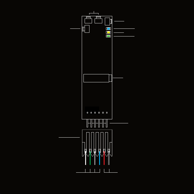
1. DMX Data Indicator
2. Function and COP 2Indicator
3. Function Button
4. SetA and SetB Buttons
5. RF Connect Indicator for Transmitter Linking
6. RF Connect (Link) Button
7. Male Connector Pins for Power In and Pixel Clock/Data Outputs
8. DMX/RDM In/Out Data Port
9. Disconnectable Female IDC Connector 1for Power In and Pixel Outputs
10. Pixel Data Connection Wires (Clock/Data1, Clock/Data2)
11. Power Connection Wires (DCin +/-)
1. Connector is Amp MTA-100-Series, 0.1” pin spacing. Shell color indicates wire gauge. Red shell is for
22 AWG wire, Amp connector P/N 3-641190-6. Numerous alternatives are available, each with dierent
P/Ns. Use the correct shell for the wire you are using. Amp also supplies crimping tools for these
connectors. One 22 AWG connector assembly is included with each LumenDimPixMicro. Additional
cable assemblies are available from RC4 Wireless.
2. COP means “Computer Operating Properly.” This indicator always shows a blink pattern,
proving that internal rmware is running. Dierent patterns indicate advanced settings.
3

4
LumenDimPixMicro Quick Start Guide
This guide will get you started using your RC4 LumenDimPixMicro.
Most LumenDimPixMicro users will nd all the information they
need right here.
Your LumenDimPixMicro also has a wide variety of expanded
features for advanced users. You can nd out more about all of them
in the RC4 Knowledge Base at http://rc4.info.
Registering Your Product
Registering your LumenDimPixMicro is quick and easy. After
registration, you’ll be notied of new rmware updates, and
warranty claims can be resolved more quickly.
Please complete your registration at:
www.rc4wireless.com/support/register/
4

55
LumenDimPixMicro System Components
To use your LumenDimPixMicro wireless pixel controller you will need:
• A DMX lighting console.
• A LumenRadio CRMX-compatible wireless transmitter like the
RC4 LumenDimIO or the LumenRadio TX1.
• A battery or DC power supply for the controller and pixel devices you will be
operating with it.
• Pixels of a type supported by the LumenDimPixMicro. Common types are
WS2812 and APA102.
MTA-100 Connector Shell Color and Wire Gauge Matter
The 6-pin connector on the LumenDimPixMicro is the Amp MTA-100-Series,
with 0.1” pin spacing. These are Insulation Displacement Connectors (IDC).
An Amp MTA-100 tool is used to insert the wires.
One 22 AWG red-shell wire-tail assembly is provided with each
LumenDimPixMicro. Additional cable assemblies are available from RC4.
The shell color of MTA connectors indicates the wire gauge it is designed for.
Red shells, Amp P/N 3-641190-6, are for 22 AWG wire. Each dierent wire
gauge uses a connector with a dierent color and P/N. Use the correct shell for
the wire you are using.
Connections to the wires on RC4 wire-tail connector assemblies can be made
by soldering, crimp connectors, wire caps, or other joiners. Be sure to cover
soldered connections with tubing or tape to avoid accidental short circuits.

66
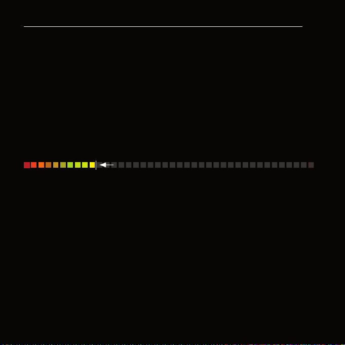
Performing a Factory Reset
If someone else has used your LumenDimPixMicro,
or you just want to get back to a known
conguration, performing a factory reset is easy:
Power on the device. The green COP indicator will
be blinking.
Press and hold Func, briey tap (press and release)
the SetA button, then release Func. COP and
Data indicators will blink together to conrm that
factory settings are restored.
NOTE: This does NOT aect transmitter linking.
You must intentionally unlink to disconnect from a
previously linked transmitter.
PRO TIP: If you are not sure what settings are
currently selected, you can always get back to
a known starting point by returning to factory
default.
RF
F
BA
RF Conn
SetA
Func
DMX Data
COP
C2 D2 C1 D1 +IN-

77
Unlink the LumenDimPixMicro
If the blue RF Connect LED on the LumenDimPixMicro blinks continuously, it is
looking for a transmitter that it was previously linked with.
To unlink it, press and hold RF Connect for several seconds until the blue LED
goes o and stays o.
If the RF Connect LED remains on, or is blinking, repeat the process until it
stays o.
When the RF Connect LED is o, the LumenDimPixMicro is ready to be linked to
your transmitter.
Link status is not aected by performing a Factory Reset. You must
intentionally unlink to disconnect from a previously linked transmitter.
NOTE: When using a wired RDM controller plugged into the miniplug DMX
connector, wireless DMX data must be stopped. This can be done by unlinking,
turning o the wireless transmitter, or disconnecting the wired DMX data going
into the transmitter.

8
Linking Transmitter and Receiver
In this example, we’re using an RC4 LumenDimIO transmitter. Have both
devices powered on. Put the LumenDimIO Mode switch in the transmit
position. Connect a DMX data source to the XLR data input on the
LumenDimIO.
Tap the Link button. This button is recessed under the small slot to the right of
the blue RF Connect LED. Tap it with a small screwdriver or the end of a bent
paperclip.
The blue RF Connect LEDs on both devices will ash for several seconds and
then remain on, indicating that they are linked.
NOTE: If DMX data is not present at the transmitter, the blue LED will blink
slowly rather than staying on.
8
MODE
PUSH
Link Button
Title
Text
99
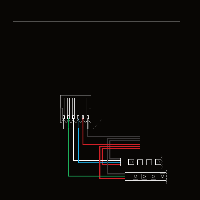
Connecting Pixel Strings and Power
To use your LumenDimPixMicro, you must connect pixel products to at
least one of the two outputs. When you’re connecting anything to your
LumenDimPixMicro, be sure that the LumenDimPixMicro is powered down.
Connect everything, being sure that the power supply delivers the correct
voltage for the pixels you are using; connecting 5V pixels to 12V power
destroys the pixels instantly.
Connections should be made to an MTA-100 connector. Attach the connector
to the LumenDimPixMicro after wiring is completed and checked, then apply
power.
Connections to wire-tail connections can be
made by soldering, crimp connectors, wire caps,
or other joiners. Wires can also be directly
inserted into a connector shell using an Amp
MTA-100 insertion tool.
One 22 AWG MTA-100
connector assembly is
incuded with each
LumenDimPixMicro.
Find additional information
about MTA-100 connectors
on page 5.
Power Input: 6 - 35VDC
Do not exceed voltage rating
for connected pixels.
The most common pixel
voltages are 5V and 12V.
-
CLK
DATA
+
-
DATA
+
4-Wire Pixels use C and D
3-Wire Pixels use Only D
Both ports support 3-wire
and 4-wire pixel types.
They can be set to dierent
types, they do not have to
be the same.
C2 D2 C1 D1 +IN-
10
10
RC4 Custom Pixel ProlesTM
The LumenDimPixMicro with patented RC4 Custom Pixel ProlesTM (CPP)
provides a simple but powerful means of creating and controlling up to
1000 pixels. RC4 CPP vastly reduces the number of channels needed, while
supporting a level of designer creativity not possible with other channel-saving
techniques. Unlike drivers that provide preset or canned eects, CPP still
allows you to create your own patterns in real time from your DMX console.
Instead of having your console handle the replication of patterns across a large
number of pixels, which consumes at least 3 channels (and sometimes more)
per pixel, that duty is moved to the pixel driver and handled by RC4 Custom
Pixel ProlesTM.
Keyframes
You decide how many DMX channels will be used for creating your pattern by
setting the Keyframe Length. A Keyframe Length of 170 pixels (the default)
will map 510 DMX channels directly to pixels, as is done with most DMX-
controlled drivers.
Setting a shorter Keyframe Length reduces the number of channels needed to
display patterns nearly identical to what an expensive console generates using
multiple universes and huge numbers of DMX channels.
The keyframe length can be anything from 1 to 170 pixels long. A particularly
powerful and channel-conservative Keyframe Length is 60 pixels*, which
utilizes just 180 DMX channels, approximately 35% of one DMX universe.
Keyframe
Tabla de contenidos


