Raspberry Pi RoboPi Manual de usuario
RoboPi v1.00 User Manual v0.60 Copyright 2014 William Henning
Using RoboPi
Copyright 2014 William Henning
RoboPi User Manual v0.60
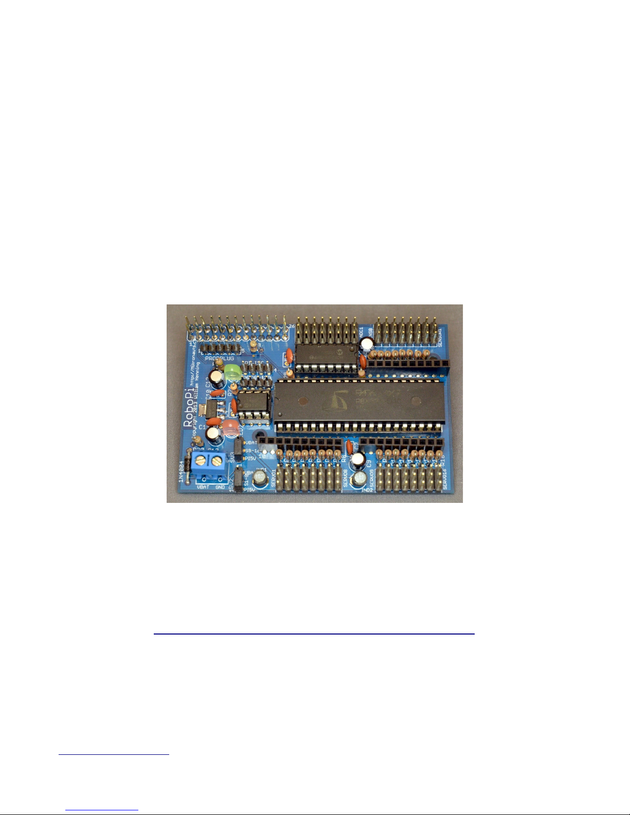
Photo 1: Fully assembled RoboPi v1.00
he most up to date documentation will always be available at:
http://www.mikronauts.com/raspberry-pi/robopi/
http://Mikronauts.com 1 2014-01-27

RoboPi v1.00 User Manual v0.60 Copyright 2014 William Henning
Table of Contents
Introduction................................................................................................................................................3
RoboPi Printed Circuit Board....................................................................................................................4
RoboPi I/O Pin Definitions........................................................................................................................5
P0-P7: SERVO 1 – SERVO 8................................................................................................................5
P8-P15: SERVO 9 – SERVO 16............................................................................................................5
P16-P23: SENSOR 1 – SENSOR 8......................................................................................................5
P24-P27: SPI port for MCP3008/MCP3208.........................................................................................5
ADC1-ADC8: 0-5V Analog inputs.......................................................................................................5
Programming RoboPi with RoboPiLib......................................................................................................6
Using the Raspberry Pi serial port with RoboPi....................................................................................6
RoboPiLib Constants.............................................................................................................................7
RoboPiLib Functions.............................................................................................................................7
Programming RoboPi with RoboPiObj......................................................................................................8
RoboPiObj Constants............................................................................................................................8
RoboPiObj Methods..............................................................................................................................8
RoboPiObj Resource Utilization...........................................................................................................8
How to use Digital Inputs..........................................................................................................................9
Reading Bumper Switches....................................................................................................................9
How to use Digital Outputs......................................................................................................................10
Using LED's to show which bumper is pressed..................................................................................10
How to use Servos....................................................................................................................................11
Controlling a Continuous Rotation Servo...........................................................................................11
Controlling a Standard Servo..............................................................................................................11
How to use PWM to control Gear Motors...............................................................................................12
EN/A/B hree Wire Driver.................................................................................................................12
A/B wo Wire interface.......................................................................................................................12
EN/DIR/PWM hree Wire Driver.......................................................................................................13
DIR/PWM wo Wire Driver...............................................................................................................13
Why the ENABLE signal of three wire drivers is useful....................................................................13
Reading Analog Distance Sensors...........................................................................................................14
Reading Digital Ultrasonic Range Sensors..............................................................................................15
Ultrasonic Sensors to be supported:....................................................................................................15
Stand-Alone Operation............................................................................................................................16
Appendix A: Software..............................................................................................................................17
Appendix B: Data Sheets.........................................................................................................................17
Appendix C: Support...............................................................................................................................17
Appendix D: RoboProp Software Compatibility:....................................................................................18
Appendix E: Frequently Asked Questions...............................................................................................19
http://Mikronauts.com 2 2014-01-27

RoboPi v1.00 User Manual v0.60 Copyright 2014 William Henning
Introdu tion
RoboPi is the most advanced robot controller add-on board for the Raspberry Pi available at this time.
RoboPi adds an eight-core 32-bit microcontroller running at 100Mhz to the Raspberry Pi in order to
off-load hard real time I/O and allow more precise timing than Linux running on the Pi allows.
RoboPi stacked on top of a odel A
Raspberry Pi
RoboPi can also be stacked on top of
odel B Raspberry Pi's
RoboPi Features
•Parallax Propeller P8X32 eight core 32 bit Risc microcontroller running at 100Mhz
•Each of the eight cores provides up to 25MIPS as most instructions take only 4 clock cycles
•three ten-pin Mikronauts I/O module expansion connectors (P0-P7, P8-P15, P16-P23)
•24 servo compatible headers on P0..P23
◦P0-P7 jumper selectable power from Pi's 5VDC supply or external servo power supply
◦P8-P15 jumper selectable power from Pi's 5VDC supply or external servo power supply
◦P16-P23 is powered by 5V from the Pi expansion header for sensors
•Screw terminal for providing external power for Servo connectors P0-P15
•8 servo compatible headers for an eight channel 0-5V analog to digital converter with choice of
◦MCP3008 for 10 bit A/D conversion
◦MCP3208 for 12 bit A/D conversion
•Choice of 256Kbit or 512Kbit boot EEPROM for the Propeller
•On-board voltage regulation providing 3.3V with power on LED from the 5V on the Pi header
•4 pin I2C expansion header for the Raspberry Pi
•4 pin I2C expansion header for the Propeller
•5 pin HCOM connector for use with PropPlug in stand alone operation (optional)
•Mikronauts EZasPi prototyping board can stack below RoboPi
•Mikronauts Pi Jumper can stack on top of RoboPi
•Mikronauts SchoolBoard ][ and other Propeller products are compatible with RoboPi
http://Mikronauts.com 3 2014-01-27

RoboPi v1.00 User Manual v0.60 Copyright 2014 William Henning
RoboPi Printed Cir uit Board
Here is a top view of where parts are located on the RoboPi printed circuit board:
You can refer to this image while wiring your robot after assembling your RoboPi.
PLEASE NOTE
he “PROPPLUG” connection is for stand-alone RoboPi operation (where RoboPi is NO stacked on
top of a Raspberry Pi. Pins 1-4 are the same as PropPlug (Pin 1 is GND), Pin 5 adds 3.3V for SerPlug.
Plugging in a PropPlug while RoboPi is sta ked on the Raspberry Pi may damage your
Raspberry Pi and/or RoboPi.
http://Mikronauts.com 4 2014-01-27

RoboPi v1.00 User Manual v0.60 Copyright 2014 William Henning
RoboPi I/O Pin Definitions
Before you can write programs for your RoboPi based robot, you have to learn what resources are
available for you to connect to sensors, motors and other devices or boards.
P0-P7: SERVO 1 – SERVO 8
•10 pin EXP1 connector connected directly to processor pins, 3v3 I/O only
•connects to signal pin on SERVO1-8 through a 2k4 current limiting resistor, 5V I/O safe
•For the servo header, SV2 selects between the Pi's 5V and VBat from the screw terminal
P8-P15: SERVO 9 – SERVO 16
•10 pin EXP2 connector connected directly to processor pins, 3v3 I/O only
•connects to signal pin on SERVO9-16 through a 2k4 current limiting resistor, 5V I/O safe
•For the servo header, SV3 selects between the Pi's 5V and VBat from the screw terminal
P16-P 3: SENSOR 1 – SENSOR 8
•10 pin EXP3 connector connected directly to processor pins, 3v3 I/O only
•connects to signal pin on SENSOR1-8 through a 2k4 current limiting resistor, 5V I/O safe
•the Pi's 5V is used for SENSOR1-8 to provide cleaner power to Ping's etc
P 4-P 7: SPI port for MCP3008/MCP3 08
•P24 is MISO, connected to DO on ADC through a 2k4 current limiting resistor
•P25 is MOSI
•P26 is CLK
•P27 is /CS
ADC1-ADC8: 0-5V Analog inputs
•connects to the signal pin on ADC1-8 servo style header
•the Pi's 5V is used for ADC1-8 to provide cleaner power to Ping's etc
http://Mikronauts.com 5 2014-01-27

RoboPi v1.00 User Manual v0.60 Copyright 2014 William Henning
Programming RoboPi with RoboPiLib
Using the Raspberry Pi serial port with RoboPi
he Raspberry Pi has 3.3V serial RX and X signals available on its 26 pin header.
Normally this port is configured to display boot messages, after which it becomes a serial console.
My favorite small text editor is 'joe', which you can install with
sudo apt-get install joe
then
sudo joe /boot/cmdline.txt
remove “console=ttyAMA0, 115200 kgdboc=ttyAMA0, 115200”
sudo joe /etc/inittab
Find the line
0:23:respawn:/sbin/getty -L ttyAMA0 115200 vt100
and insert a '#' in front of 0:23
For the changes to take effect, type
sudo shutdown now -r
http://Mikronauts.com 6 2014-01-27

RoboPi v1.00 User Manual v0.60 Copyright 2014 William Henning
RoboPiLib Constants
Digital pins can be configured for one of the following four modes:
INPU pin mode for a digital input
OU PU pin mode for a digital output
PWM pin mode for a PWM output (0..255)
SERVO pin mode for a servo output (0..2500)
RoboPiLib Functions
void RoboPiInit(char *device, int bps) use RoboPiInit(“/dev/ttyAMA0”,115200)
void RoboPiExit() close the serial connection with RoboPi
int readMode(int pin) returns INPU /OU PU /SERVO/PWM
void pinMode(int pin, int mode) set pin to one of INPU /OU PU /SERVO/PWM
int digitalRead(int pin) returns 0 or 1 state of pin
void digitalWrite(int pin, int val) sets pin to 0 or 1
int analogRead(int chan) returns 0..1023 from specified channel
int analogReadRaw(int pin) returns 0..4095 from specified channel
void analogWrite(int pin, int val) write 0..255 to PWM pin (off to full on)
int servoRead(int pin) return last servo value written to pin
void servoWrite(int pin, int val) set servo on pin to val (0..2500 us)
In your program, include “RoboPiLib.h”, and add RoboPiLib.o to your command line as follows:
gcc -o myprog myprog.c RoboPiLib.o
http://Mikronauts.com 7 2014-01-27

RoboPi v1.00 User Manual v0.60 Copyright 2014 William Henning
Programming RoboPi with RoboPiObj
RoboPiObj Constants
INPU pin mode for a digital input
OU PU pin mode for a digital output
PWM pin mode for a PWM output (0..255)
SERVO pin mode for a servo output (0..2500)
RoboPiObj Methods
start Initialize RoboPiObj, start service cogs
pinMode(pin, mode) set digital pin to specified mode
readMode(pin) read current mode of digital pin
digitalRead(pin) read current value (0 or 1) at pin, regardless of mode
digitalWrite(pin) write 0 or 1 to digital pin
analogRead(chan) read analog input channel, scale to 0..1023 return value
analogReadRaw(chan) read analog input channel, return raw 0..4095 value
analogWrite (pin, value) write PWM value to pin, 0 is off, 255 is fully on
servoWrite(pin, value) write servo position to pin , 0 to 2500 microseconds
servoRead(pin, value) return last servo position written to pin
delay(ms) delay for ms milliseconds
delayMicroseconds(us) delay for us microseconds
RoboPiObj Resource Utilization
RoboPiObj uses 4944 bytes of EEPROM/RAM and two cogs for drivers,
ADC_INPU _DRIVER MCP3208 driver object
PWM_32_v4 PWM/Servo driver object
http://Mikronauts.com 8 2014-01-27

RoboPi v1.00 User Manual v0.60 Copyright 2014 William Henning
How to use Digital Inputs
Reading Bumper Switches
Probably the simplest digital input possible is a switch.
<insert schematic of two bumper switches, 10k pullup to 5v, shorts to ground when closed>
#include “stdio.h”
#include “RoboPiLib.h”
#define LEF _BUMPER 0
#define RIGH _BUMPER 1
#define PRESSED 0
int main(int argc, char *argv[]) {
pinMode(LEF _BUMPER, INPU );
pinMode(RIGH _BUMPER, INPU );
while (1) {
if (digitalRead(LEF _BUMPER)==PRESSED)
puts(“Left Bumper Pressed”);
if (digitalRead(RIGH _BUMPER)==PRESSED)
puts(“Right Bumper Pressed”);
sleep(1); // only check once per second
}
}
http://Mikronauts.com 9 2014-01-27

RoboPi v1.00 User Manual v0.60 Copyright 2014 William Henning
How to use Digital Outputs
he simplest way of demonstrating a digital output is to use it to light an LED.
Using LED's to show which bumper is pressed
<insert schematic of two LED's connected to EXP pins through 470R resistors>
#include “stdio.h”
#include “RoboPiLib.h”
#define LEF _BUMPER 0
#define RIGH _BUMPER 1
#define LEF _LED 2
#define RIGH _LED 3
#define PRESSED 0
int main(int argc, char *argv[]) {
pinMode(LEF _BUMPER, INPU );
pinMode(RIGH _BUMPER, INPU );
pinMode(LEF _LED, OU PU );
pinMode(RIGH _LED, OU PU );
while (1) {
digitalWrite(LEF _LED, ~digitalRead(LEF _BUMPER));
digitalWrite(RIGH _LED, ~digitalRead(RIGH _BUMPER));
}
}
http://Mikronauts.com 10 2014-01-27
Otros manuales para RoboPi
1
Tabla de contenidos
Otros manuales de Placa madre de Raspberry Pi


Manuales populares de Placa madre de otras marcas


Telit Wireless Solutions
Telit Wireless Solutions SL869-3DR Manual de usuario

Gigabyte
Gigabyte GA-9IVDT Manual de usuario

Texas Instruments
Texas Instruments ADS8372EVM Manual de usuario

Commell
Commell MS-C73 Manual de usuario

IBT Technologies
IBT Technologies MB860 Manual de usuario

Nvidia
Nvidia TEGRA DG-04927-001_V01 Manual de usuario


