Range Road RR27T Manual de usuario

Range Road RR27T
Firewood Processor
Crated Unit
Assembly Manual

RR27T
Range Road Enterprises Ltd
Box 944
Eckville AB T0M 0X0
www.range-road.ca
Page 2
Crated Unit
1.) Undo 8 -18mm x 19mm Nuts and bolts , 2 on each leg of top frame
2.) Lift top of Metal crate off and move out of work area.
3.) Remove Shrinkwrap.
4.) Unwrap Wheels
5.) Remove bag containing Bearing, washer, nut, cotter key and cap, place
on workbench, set unwrapped wheels out of the way.
6.) Unwrap the following, place on workbench
sawdust chute

RR27T
Range Road Enterprises Ltd
Box 944
Eckville AB T0M 0X0
www.range-road.ca
Page 3
sawbar engagement arm and extension
toolbox
fenders (2)
bar oil container, do not misplace the loose hose
towbar jack
Log roller Arm
Towbar
Splitter Wedge, Axle
Chainsaw Bar Cover, Safety Cages (2), Hydraulics Cover
The Processor should now be sitting on the crate with all loose pieces
removed

RR27T
Range Road Enterprises Ltd
Box 944
Eckville AB T0M 0X0
www.range-road.ca
Page 4
7.) Lift processor off crate with forklift, crane or jacks, make sure that
straps will not catch anything on unit when tightened and that unit will be
balanced.
Lift high enough to be able to install Axle, Wheels and Tripod
8.) Remove lower crate from work area
9.) Install Tripod leg at front of processor
10.) Loosen Axle retention Bolts and lock nuts (18mm x 18mm)
11.) Slide Axle through tube, make sure the bolt holes face upwards,
centre the axle in the housing, tighten bolt, tighten lock nut, repeat on
opposite side
12.) Grease all 4 wheel bearings, use a flat screwdriver to remove dust
seals from hubs and remove inner wheel bearings for greasing
13.) Install Wheel on axle

RR27T
Range Road Enterprises Ltd
Box 944
Eckville AB T0M 0X0
www.range-road.ca
Page 5
14.) Install Bearing, then washer
15.) Screw on Castle Nut make sure to line threads up
16.) Tighten castle nut until nut is snug and wheel is hard to turn, then
back the nut off ¼ turn until cotter pin hole lines up
17.) Insert cotter pin and bend
18.) Install hub cap, use a rubber mallet to press into place
19.) Grease wheel hub generously through grease zerk on back of hub
Repeat on opposite side
20.) The four lug nuts of each wheel should be torque to 90ft-lbs
.
Lower unit to floor
Assembler must check that the engine and hydraulic couplers
are secure and spaced properly
RR27T
Range Road Enterprises Ltd
Box 944
Eckville AB T0M 0X0
www.range-road.ca
Page 6
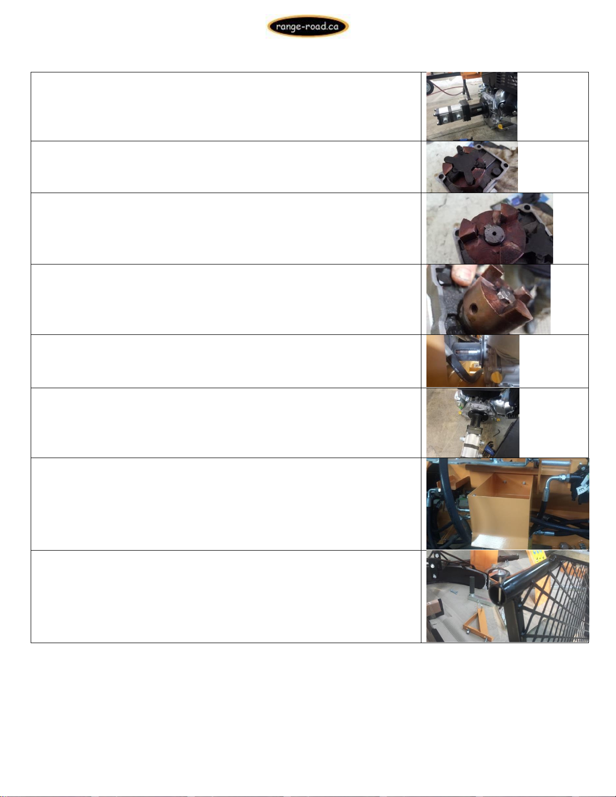
21.) Main pump should be removed to check this.
Ensure that Lovejoy rubber is not damaged
If the crankshaft or hydraulic pump shaft sticks through the coupler to get
the right fitment, make sure that the rubber is turned so the shaft fits
into the hollow. Make sure that the keyway does not distort the rubber, if
the keyway is protruding as pictured it will damage the rubber, it must be
pushed down to be level with coupler edge
You should not see the keyway above the coupler. As shown in the picture
the keyway must be tapped down, flush with the coupler
22.) Line the Lovejoy connectors up and trial fit the pump to the motor,
adjust the lovejoys so that there is a small space in between the metal
couplers (approximately 1/16”)
23.) Tighten the bolts holding the housing to the engine and recheck the
spacing on the lovejoy
24.) Install sawdust chute 10mm Nut x Bolt through body, nuts go in the
sawdust collector side.
25.) Remove cotter pin from bottom tube on large safety cover

RR27T
Range Road Enterprises Ltd
Box 944
Eckville AB T0M 0X0
www.range-road.ca
Page 7
26.) Remove 8 –10mm Nuts and bolts from edge of large safety cover.
27.) Line up holes in edge of large safety cage with the holes in the side of
the chainsaw cover
28.)Install 8 –10mm bolts and nuts, tighten
29.) Install Bar Oil Tank onto back of chainsaw safety cover with 13mm nut
30.) Remove 10mm bolt and nut from holder above splitting trough, keep
plastic tube as well
31.) Put large safety cage cover into place, slide through hole in processor
32.) Re-install 10mm Bolt, tubing and nut, snug up lock nut, do not tighten
33.) Remove nut from bar lube fitting, insert hose over barb and snug up
fitting (14mm)

RR27T
Range Road Enterprises Ltd
Box 944
Eckville AB T0M 0X0
www.range-road.ca
Page 8
34.) Route hose through hole in cover to bar oil tank, remove nut, insert
hose over barb and snug up fitting (14mm)
35.) Remove nut from Bar Oil tank fitting, insert hose through nut and over
barb, snug up nut over hose
36.) The chain can now be adjusted to ensure the tension is set
correctly. Proper chain tension
i
s achieved when the chain can be
pulled away from the bar by hand ¼”
--
‐
½”. To tighten or
l
oosen the
chain, the two bolts can be loosened using a 12mm wrench. Next, the
allen key bolt can be turned clockwise to tighten or counter
--
‐
clockw
i
se
to loosen the chain. The two 12mm bolts can be tightened again to
hold the bar secure
l
y
.
37.) Hook sawbar return spring into slot.
38.) Apply grease liberally to the metal surfaces that touch below the
spring, this will help them slide

RR27T
Range Road Enterprises Ltd
Box 944
Eckville AB T0M 0X0
www.range-road.ca
Page 9
39.) Remove 2 10mm Nuts & Bolts and plastic tubing for small safety cover
mount
40.) Set small safety cage in place, re-install 10mm bolts nuts and tubing
41.) Bolt roller travel mount to processor, 2 –13mm bolts and nuts (mount
may be in Toolbox)
42.) Mount toolbox, 2 –13mm bolts and nuts
43.) Position & tighten chainsaw actuator tab so it will activate valve when
moved, can adjust later if needed
44.) Adjust bolt on swivel plate (in black circle) so that when the sawbar is
pulled down the bolt head hits the body to stop the swivel plate, this will
allow the chainsaw to cut through the log but stops it from going further
and stretching the cable.
45.) Adjust cable so that when the chainsaw bar is pulled down, the cable
will activate the ram valve, to tight and the cable will stretch, to loose and
the ram won’t activate. The cable can be adjusted at both ends.

RR27T
Range Road Enterprises Ltd
Box 944
Eckville AB T0M 0X0
www.range-road.ca
Page 10
46.) Find the ends of the 4 Hydraulic hoses that are not hooked up
47.) Connect hydraulic hose to saw motor, make sure hose is routed cleanly
and not rubbing, connect marked Hoses to corresponding port, “A” to “A”,
“H” to “H”,etc.( some Units will already have this connected
Make sure all hoses are routed cleanly and will not rub
48.) Undo 17mm nuts on engine mount bolts and apply Loctite, re-tighten
49.) Remove 10mm nut, lockwasher and flatwasher from starter solenoid,
Install loop from red wire onto stud of solenoid and re-install washer and
nut, do not overtighten nut
.
Otros manuales de Partidor de troncos de Range Road


Manuales populares de Partidor de troncos de otras marcas


Scheppach
Scheppach OX 3-1000 Instrucciones de montaje

Swisher
Swisher 21200 Manual de usuario

Elem Garden Technic
Elem Garden Technic FBHT65-22TCH Manual de usuario

Champion Power Equipment
Champion Power Equipment 90720 Manual

Boss Industrial
Boss Industrial ES5T20 Manual de usuario

Villager
Villager LSP 12 T Manual de usuario


