Racer Direct Manual de usuario

R
AC
ER
®
-

Contents
Page
Product Overview ....................................................................................... 3 - 5
Electrical Connection ................................................................................ 6 - 7
Wiring Diagrams ....................................................................................... 39
2
Flow Requirements .................................................................................... 8
Operating Instruction ............................................................................... 9 - 13
Troubleshooting ....................................................................................... 16 - 18
Warranty ..................................................................................................... 19
Dedicated RCD .......................................................................................... 14
Quick Functional Test .............................................................................. 15
Dedicated RCD Wirind Diagram .......................................................... 38
ENGLISH
3
Important Instructions
Congratulations.
You have just purchased the Racer Direct electric swimming pool
heater manufactured to the highest standards in England.
To ensure years of trouble free service, please read and follow
these instructions for proper installation, maintenance and use.
Please retain this manual for future reference.
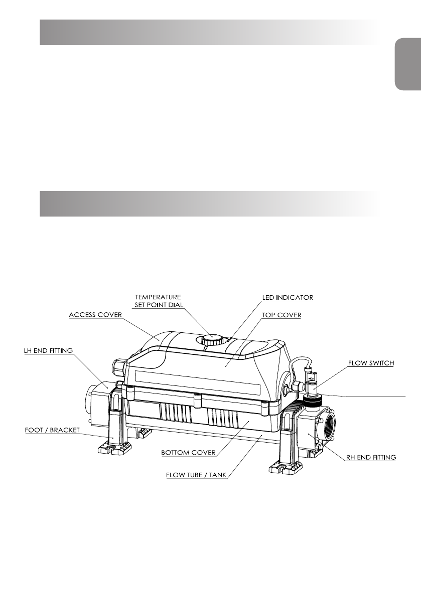
Product Overview
Fig 1.
TEST BUTTON
ENGLISH
4
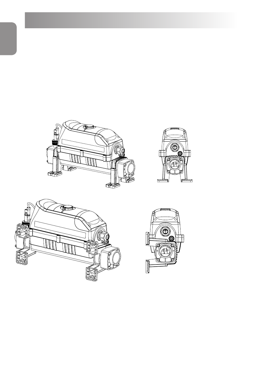
Your heater should be located either horizontally or vertically allowing
sufficient space for pipe connections and wiring, it should be secured
firmly using screws to a firm base or wall.
NOTE: See Fig. 2 for mounting instructions when securing to the wall
or floor.
The heater should be installed at a low point in the ltration system.
It should be positioned downstream of (after) the lter and upstream of
(before) any dosing or other water treatment plant. (see g.3)
Floor mount
Wall mount
Fig 2.
Product Overview
ENGLISH

5
Flow switch
at top
For vertical wall mounting
water must always enter
at the bottom
Fig 3.
Fig 4.
FILTER
PUMP RACER HEATER
POOL
NON RETURN
VALVE
UV SYSTEM
ENGLISH

6
Pipe Work
It is essential that the pipe work connecting to and from the heater has a
minimum bore (internal diameter) of 32 mm. To support correct air
purging and to ensure the heater remains completely full of water during
operation; the return pipe which carries the water back to the pool must
incorporate a safety loop or ‘kick-up’ in the pipe as close as possible to
the heater (see Fig.4)
NOTE: When coupling to a flexible pipe a safety loop can easily be
formed by directing the pipe up and over an obstacle. Pipe clips
should be used to securely fasten all hose connections.
Weather Protection
The heater must be installed within a dry weather proof area.
Caution! If the heater is unused during the winter months, it must be
drained to prevent frost damage.
Electrical Connection
The heater must be installed in accordance with the country / regional
requirements and regulations. In any event the work must be carried out
by a qualified electrician, who will provide a certificate of conformity upon
completion of the work. The power supply must be fitted with an RCD. If
required, your electrician may replace the cable entry gland supplied with
a larger size to secure the cable powering the heater. This will not affect
your warranty if undertaken by a qualified electrician.
Cable section: This should be calculated at 5-amp / mm² for distances
up to 20 metres (these sections are indicative and should be checked
and adapted if necessary for cable lengths over 20 metres).
ENGLISH

Remove Access Cover
to make the electrical
connections
(Qualifi d electricians only)
Fig 5.
Power Requirements
Power
Output
Voltage
(V) Amp
3- kW 230 13
6- kW 230 27
9- kW 230 40
12- kW 230 53
15- kW 230 66
18- kW 230 79
3 Phase
Power
Output
Amp
6 - kW 400 9
9 - kW 400 13
12 - kW 400 18
15 - kW 400 22
18 - kW 400 26
24 - kW 400 35
Voltage
(V)
7
ENGLISH

8
Flow Requirements
The heater can accept the flow of water from either end, but only by
rotating the heater 180⁰. (See Fig. 6).
DO NOT REVERSE THE FLOW SWITCH.
Left to Right
Flow direction
Fig 6.
The flow rate of water into the heater must not exceed 17,000 litres per
hour (17m3 / hour / 3,740 UK gallons per hour). A higher flow rate will
require the installation of a bypass to prevent damage to the heater
elements. The heater will not operate unless the following minimum flow
rates are achieved:
1,000 litres / hour (1m3/hour / 220 UK gallons/hour) for 2 ~ 6-kW heaters
4,000 litres / hour (4m3/hour / 880 UK gallons/hour) for 9 ~ 24-kW heaters
Water Quality
The water quality MUST be within the following limits:
PH 6.8 - 8.0
TA (Total alkalinity) 80—140ppm (parts per million)
Chloride Content MAX: 150 mg/litre
Free Chlorine: 2.0 mg/litre
Total Bromine: Max 4.5 mg/litre
TDS (Total Dissolved Solids) / Calcium hardness 200— 1,000ppm
Stainless Steel heaters are NOT suitable for use on saline (salt) water pools.
ONLY heaters with titanium heating elements are suitable for use on saline
(salt) pools.
ENGLISH

9
Operating Instructions
Upon completion of the installation, run the water-circulating pump to
purge the system and heater of air (i.e. remove any trapped air in the
system & heater). TIP: You can encourage air out of the heater ow tube by
gently elevating the exit port of the heater when the pump is running.
On initial power up of the heater the amber light should illuminate.
The heater will only switch ‘On’ (red light indicator illuminated) when
the following criteria are met:
•Water circulating pump is ‘On’ delivering more than the minimum
flow rate of water (see flow requirement information)
•The required water temperature point is set to a higher value
than that of the water
Selector knob operation:
To aid navigation through the controller options, the digital heater
is fitted with a selector knob for easy and user-friendly navigation.
To adjust or select any option simply turn the knob clockwise or
anticlockwise (see Fig.7).
To confirm selected option, press the knob button (OK). The display
should show message ‘SAVED’ confirming the changes (see Fig.8).
ENGLISH
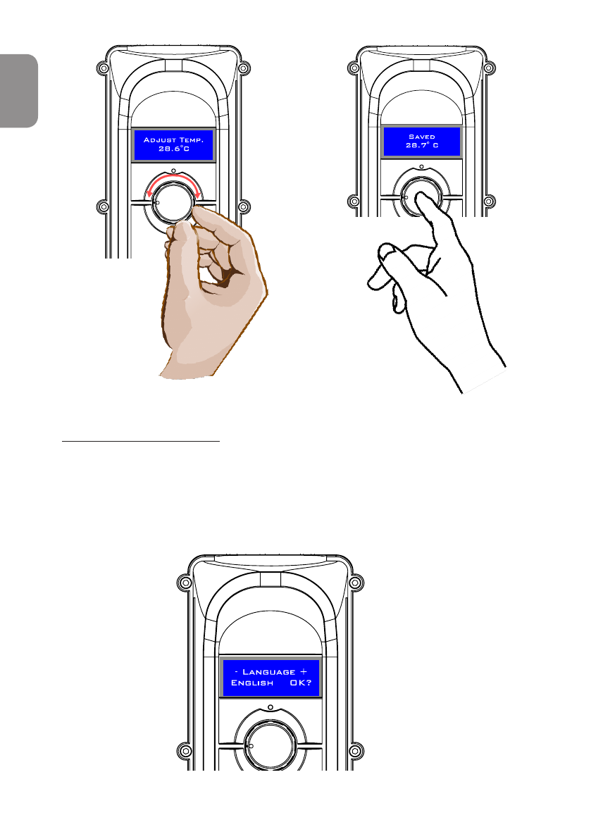
Choose your language:
On initial power up, the display will illuminate and show a language
message (Fig.9). If the controller detects inactivity for 3 seconds, it
will default the language to English.
Fig 7. Fig 8.
Fig 9.
10
ENGLISH
Tabla de contenidos
Idiomas:
Manuales populares de Calentador de piscina de otras marcas


Pentair Pool Products
Pentair Pool Products MiniMax CH 150 Manual de usuario

Jandy
Jandy LJ Manual de usuario

Pentair Pool Products
Pentair Pool Products MiniMax NT Series Manual de usuario

Raypak
Raypak P-R185A to P-R405A, C-R185A to Manual de usuario

Hayward Pool Products
Hayward Pool Products HP40A Manual de servicio

Laars
Laars Lite 2 LC Manual de usuario


