Quick BT QSY Series Manual de usuario

REV 001B
BT QSY Series
BT QSY 140
BT QSY 185
BT QSY 250
BT QSY 300
SINGLE AND DOUBLE PROPELLER - SYNCHRONOUS MOTOR
*EN - INSTALLATION AND USER'S MANUAL *Other languages available by scanning the QR code on the
back of this manual or on the label on the product.


BT QSY Series EN
INDEX
QUICK BTQSYSERIES INSTALLATION AND USER’S MANUAL - REV001B
1 - Information about the product 5
1.0 - Technical Data 5
2 - Supply and equipment 6
2.0 - Standard supply and material included in the package 6
2.1 - Tools required for installation 6
2.2 - Compatible Quick®remote control systems not included 6
2.2 - Recommended Quick®accessories not included 6
3 - Introduction 7
3.0 - Important notes 6
3.1 - Precautions 7
3.2- Precautions for the installer 7
3.3 - Installation requirements 7
4 - Installation 8
4.0 - Propellers 8
4.1 - Tunnel 9
4.2 - Thruster 10
4.4 - BT QSY 140/185/250/300 Gearleg and motor support flange 11
4.4.0 - Single & double propeller assembly 11
5 - Cautions & Use 15
5.0 - General BT QSY basic system, AMC connection 12
5.1 - General BT QSY basic system, PCS connection 13
5.2 - General BT QSY basic system, TCD connection 14
5.0 - Important cautions 15
5.1 - Thruster use 15
6 - Maintenance 16
6.0 - Single/double propeller maintenance 16
7 - Product disposal 16
7.0 - Product disposal 16
8 - Spare parts 17
8.0 - BT QSY 140/185 17
8.1 - BT QSY 250/300 18
9 - Dimensions 19


BT QSY Series EN
QUICK BTQSYSeries INSTALLATION AND USER’S MANUAL - REV001B
5
1.0 - Technical Data
MODELS BT QSY 140-45 BT QSY 185-85 BT QSY 185-85 BT QSY 185-100
Propeller type Single
(technopolymer) 2 Counter rotating (technopolymer)
Tunnel Ø 140 mm (5” 1/2) 185 mm (7” 9/32) 185 mm (7” 9/32) 185 mm (7” 9/32)
Motor power 2.5 kW 4 kW 8 kW
Voltage 12 V 12 V 24 V 24 V
Fuse 175 A CNL DIN 275 A CNL DIN 150 A CNL DIN 175 A CNL DIN
Thrust 45 kgf (99.2 lb) 85 Kgf (187.4 lb) 100 kgf (220.5 lb)
Weight 14.5 kg (31 lb) 16.6 kg (36.6 lb) 16.5 kg (36.6 lb)
Tube thickness limit value min. 4.5 mm - max 6.5 mm (min. 11/64” - max 1/4”)
Recommended
cable cross-
section
(*)
(**)
L < 5 m 50 mm2
(AWG 1)
95 mm2
(AWG 3/0)
35 mmq
(AWG 2)
50 mm2
(AWG 1)
5.1 < L < 10 m 50 mm2
(AWG 1)
95 mm2
(AWG 3/0)
35 mmq
(AWG 2)
50 mm2
(AWG 1)
10.1 < L < 20 m 70 mm2
(AWG 2/0)
95 mm2
(AWG 3/0)
35 mmq
(AWG 2)
50 mm2
(AWG 1)
MODELS BT QSY 250-140 BT QSY 250-200 BT QSY 300-240 BT QSY 300-300
Propeller type 2 Counter rotating (technopolymer) 2 Counter rotating
(nibral)
Tunnel Ø 250 mm (9” 27/32) 250 mm (9” 27/32) 300 mm (11” 13/16) 300 mm (11” 13/16)
Motor power 8 kW 12 kW 12 kW 16 kW
Voltage 24 V 24 V 48 V 48 V
Fuse 250 A CNL DIN 400 A CNL DIN 200 A CNL DIN 275 A CNL DIN
Thrust 140 kgf (308 lb) 200 kgf (440.9 lb) 240 kgf (529.1 lb) 300 kgf (660 lb)
Weight 34.3 kg (75.6 lb) 39.6 kg (87.3 lb) 56.8 kg (125.2 lb) 62 kg (136.7 lb)
Tube thickness limit value min. 6.5 mm - max 11 mm (min. 1/4” - max 7/6”) min. 9.5 mm - max 13.5 mm
(min. 3/8” - max 17/32”)
Recommended
cable cross-
section
(*)
(**)
L < 5 m 70 mm2
(AWG 2/0)
2x70 mmq
(2xAWG 2/0)
70 mm2
(AWG 2/0)
95 mm2
(AWG 3/0)
5.1 < L < 10 m 70 mm2
(AWG 2/0)
2x70 mmq
(2xAWG 2/0)
70 mm2
(AWG 2/0)
95 mm2
(AWG 3/0)
10.1 < L < 20 m 70 mm2
(AWG 2/0)
2x70 mmq
(2xAWG 2/0)
70 mm2
(AWG 2/0)
95 mm2
(AWG 3/0)
(*) L = positive cable + negative cable
(**) Other solutions are allowed, provided that they are supported by the connecting terminals. Respect minimum cross-section
indicated.
READ THIS INSTRUCTION MANUAL CAREFULLY BEFORE USING THE PRODUCT. IF IN DOUBT, CONTACT YOUR QUICK®
DEALER.
QUICK®RESERVES THE RIGHT TO MODIFY THE TECHNICAL CHARACTERISTICS OF THE EQUIPMENT AND THE CONTENTS OF THIS MANUAL WITHOUT
PRIOR NOTICE. IN CASE OF DISCORDANCE OR ERRORS IN TRANSLATION BETWEEN THE TRANSLATED VERSION AND THE ORIGINAL TEXT IN THE ITALIAN
LANGUAGE, REFERENCE WILL BE MADE TO THE ITALIAN TEXT.
1 - Information about the product

EN BT QSY Series
QUICK BTQSYSeries INSTALLATION AND USER’S MANUAL - REV001B
6
2.0 - Standard supply and material included in the package
• Thruster
• Drilling template
• Gasket
• O-ring
• Installation and use manual
• Conditions of warranty
• QSY ON/OFF interface (ON/OFF models only)
• Adapter M12-23 poles (only for 250/300)
• TCD QSY wiring cable (ON/OFF models only)
2.1 - Tools required for installation
BT QSY140 • Drill and drill bits Ø 7 mm (9/32”)
• Hollow mill Ø 27 mm (1” 1/16)
• Male hex.wrenches: 4 mm, 5 mm and 6 mm
• Fork wrench: 17 mm
BT QSY185 • Drill and drill bits Ø 9 mm (3/8”)
• Hollow mill Ø 35 mm (1” 3/8)
• Male hex.wrenches: 5 mm, 6 mm and 8 mm
• Fork wrench: 19 mm
BT QSY250 • Drill and drill bits Ø 11 mm (7/16”)
• Hollow mill Ø 46 mm (1” 13/16)
• Male hex.wrenches: 4 mm, 5 mm, 8 mm and 10 mm
• Fork wrench: 24 mm
BT QSY300 • Drill and drill bits Ø 15 mm (19/32”)
• Hollow mill Ø 53 mm (2” 3/32)
• Male hex.wrenches: 4 mm, 5 mm, 8 mm and 12 mm
• Fork wrench: 27 mm
2.2 - Compatible Quick®remote control systems not included
• TCD (ON/OFF models)
• PCS (system)
• AMC (system)
2.2 - Recommended Quick®accessories not included
• AMC EX cable
• AMC QSY ADP cable
• PCS QSY ADP cable
• QSY EX cable
• PCS QSY ADP
• TCD SP cable
• TCD EX cable
2 - Supply and equipment
3.0 - Important notes
BEFORE USING THE PRODUCT, PLEASE READ THIS USER’S MANUAL CAREFULLY. IF IN DOUBT, PLEASE CONSULT YOUR QUICK® DEALER.
This manual features Warning and/or Caution symbols that are important for safety.
Please follow the instructions provided.
Warning symbol for dangerous
situations.
Caution symbol to prevent direct or
indirect damage to the product.
This manual provides boat manufacturers and nautical equipment installers with instructions on how to assemble the specied
Quick®product and operate it correctly.

EN
BT QSY Series
QUICK BTQSYSeries INSTALLATION AND USER’S MANUAL - REV001B
7
3.1 - Precautions
Quick®Thrusters have been designed and constructed only for nautical use.
• Do not use these products for any other type of operation.
• Quick®shall not be held liable for direct or indirect damage caused by improper use of the product.
• The product is not designed to support loads generated in particular atmospheric conditions (storms).
• Operate the product from a position where it is possible to supervise the work area.
• Always deactivate the product when not being used.
• For improved safety, we recommend installing at least two controls to operate the product in case one is damaged.
• The installer shall bear full responsibility for any problems caused by defective installation of the tunnel.
• This equipment is not intended for use by people (including children) with reduced physical, sensory or mental capabilities.
• Do not install the electric motor near easily inammable objects.
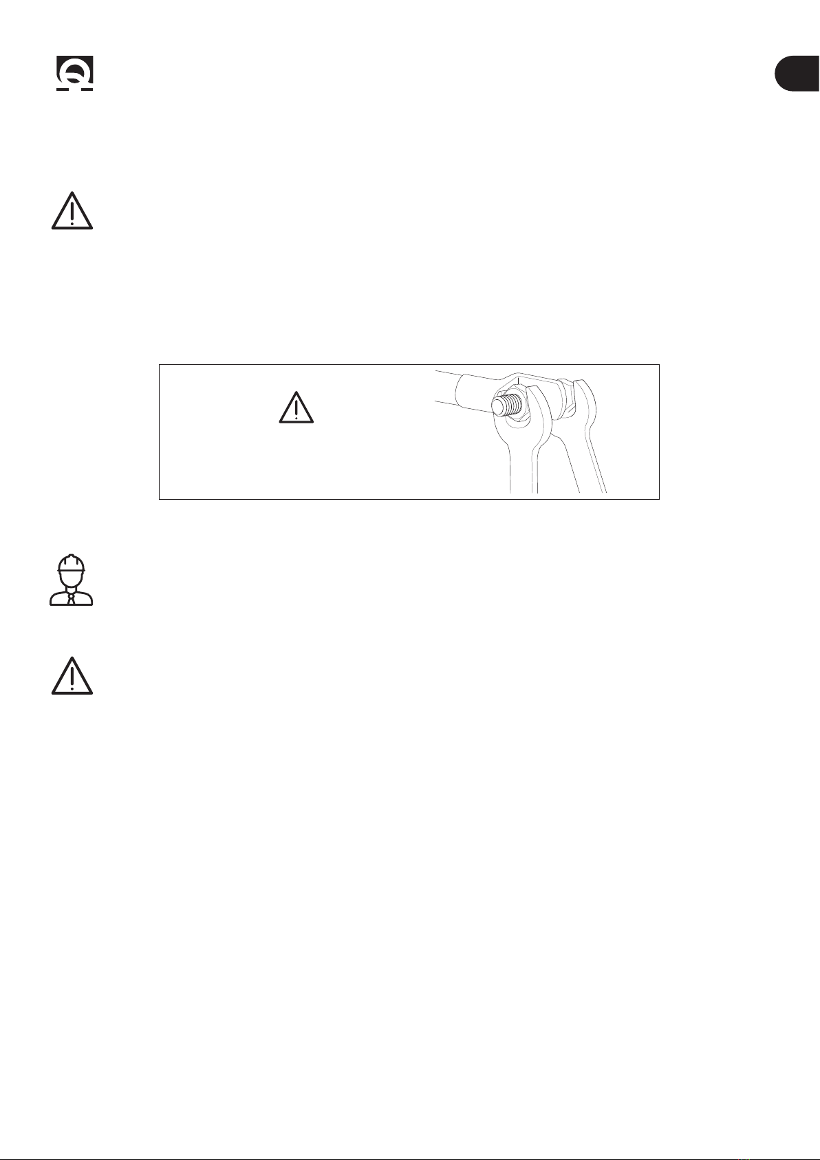
The terminals must be properly tightened.
Secure / hold the inner nut when tightening
MINIMUM TIGHTENING TORQUE IS 11 Nm
3.2- Precautions for the installer
CARRY OUT THE INSTALLATION IN GOOD LIGHTING CONDITIONS.
It is advisable to wear suitable clothing and personal protective equipment (PPE).
The product is not suitable for installation in potentially explosive environments and/or atmospheres.
Installation and subsequent inspection or repair work must only be carried out by qualied personnel.
CARRY OUT INSTALLATION/MAINTENANCE WORK MAKING SURE THAT THE PRODUCT IS DISCONNECTED
FROM THE ELECTRICAL SYSTEM.
Quick®accepts no responsibility for inadequate connection of users to the electrical system and inadequate safety of
the electrical system.
3.3 - Installation requirements
We recommend you entrust preparation and positioning of the tunnel in the hull to a skilled professional.
These are generic instructions and do not give details of the preparatory operations for installing the thruster, since this is the
competence of the boatyard. The installer shall bear full responsibility for any problems caused by defective installation.
Although all the components and mechanical moving parts are of high quality, the correct installation of the driving unit is an
essential basis for the safe and effective use of the boat as well as the driving unit itself.
The installation of such a unit is an operation that requires experience as well as technical skills. It is recommended that the
installation be carried out by competent personnel and that the manufacturer or naval architects be consulted to fully assess
the scope of the work.
3 - Introduction

BT QSY Series
EN
QUICK BTQSYSeries INSTALLATION AND USER’S MANUAL - REV001B
8
4 - Installation
4.0 - Propellers
The position of the tunnel will depend on the interior
and exterior shape of the boat’s bow.
• FIG. 1 In order to avoid cavitation in the propeller, the
tunnel should be placed as deep as possible. The optimum
tunnel position will be at least 0.75 times the diameter of
the tunnel from the waterline.
B
L1
L2
A
BARYCENTRE
FIG. 2
• FIG. 2 The lever effect in the boat is proportional to
the increase of the distance (L1 and L2) between the
barycentre and the position of the tunnel A and B.
• FIG. 3 For greater lever effect prefer position B.
SINGLE PROPELLER DOUBLE PROPELLER TUNNEL LENGTH
MINIMUM 1.5 TIMES
TUNNEL Ø
MAXIMUM 6 TIMES
TUNNEL Ø
An increase in the length of the tunnel increases the effect of the loss of charge, decreasing the nominal driving force.
• For a proper use of the thruster, we recommend a length equal to 1.5 to 4 times the tunnel diameter. To limit losing charge, a
ratio of up to 6 times the diameter can be tolerated.
Minimum 0.75
times tunnel Ø
FIG. 1

BT QSY Series EN
QUICK BTQSYSeries INSTALLATION AND USER’S MANUAL - REV001B
9
4 - Installation
4.1 - Tunnel
• The rounded ends of the tunnel limit the creation of turbulence and cavitation, improving performance of the propeller thrust
and reducing noise levels to a minimum.
SINGLE PROPELLER
DOUBLE PROPELLER
• The force produced by the ow of the water when the boat is moving produces resistance on the rear face of the tunnel,
which is an area exposed frontally to the water ow. To limit this phenomenon, prepare an indentation in the rear part of the
tunnel. The indentation will depend on the shape of the hull. Otherwise, create a deector on the front part of the tunnel.
• If the tunnel is near the waterline, it is advisable to t a grating at the end of the tube. The
grating must have as large a vertical mesh as possible to avoid contrasting the propeller thrust.
The vertical mesh prevents the entry of most of the oating objects.

BT QSY Series
EN
QUICK BTQSYSeries INSTALLATION AND USER’S MANUAL - REV001B
10
4 - Installation
4.2 - Thruster
• The thruster can be installed at any angle within 90º from
the vertical.
• If the electric motor is positioned at an angle of more than
30° from the vertical, an appropriate support (saddle) must be
installed.
SINGLE PROPELLER DOUBLE PROPELLER
• To position the thruster in the tube, nd the half-way point
of the tube and move by the value indicated (left or right, see
box) in the diagram below so that the propeller is positioned
exactly in the middle of the inner length of the tunnel.
• To position the thruster in the tube, nd the half-way point
of the tube and move by the value indicated (left or right, see
box) in the diagram below so that the propeller is positioned
exactly in the middle of the inner length of the tunnel.
10 2 3 4 5 6 7 8 9 10
10 2 3 4
10 2 3 4
BT QSY 140 50 mm
10 2 3 4 5 6 7 8 9 10
• Use the ange to mark the centre of the holes on the tube.
• Fix the drilling template on the reference points, making
sure they are aligned with precision at the half-way point of
the tube.
N.B. All holes must be exactly aligned with the half-
way point of the tunnel, since tolerance between
propeller and tunnel is minimal.
• Take care that there are no resin residues in the contact
area between ange and tube; this could cause misalignment.
Any resin residues and any other hindrance to correct
contact must be removed with sandpaper.
BTQ SY Ø140/185/250/300
• Insert two O-rings into the special seats inside the ange.
Este manual sirve para los siguientes modelos
4
Tabla de contenidos
Otros manuales de Motor de Quick


