QC Conveyors FLEXTRAC Series Manual de usuario

Model Number __________________________
Serial Number __________________________
Date of Install __________________________
For ease of reference please fill out your conveyor’s specific information above
FLEXTRAC SERIES MANUAL
Installation & Maintenance
MAN-FT-2002
4057 Clough Woods Drive
Batavia, OH 45103 USA
+1 (513) 753–6000
qcconveyors.com
CONTENTS
Introduction page 2
Tools & Fasteners page 3
Assembly page 4
Plastic Belt Installation page 17
Start up & Testing page 18
Introduction to Maintenance page 20
Conveyor Chains page 26

2 | Installation Site Preparation — Introduction to Installation | Flextrac Series
Installation Site Preparation INTRODUCTION TO INSTALLATION
The purpose of this manual is to help the end user to assemble a Flextrac Series conveyor system. Every chapter includes detailed
instructions and photos showing how to assemble each component. Most photos in this manual include parts from MM3 conveyor
system, but all instructions are applicable to MS2, ML2, and MX2 conveyor system unless otherwise specied or noted.
Assembly Planning
Fully understand the assembly drawing.
Ensure the necessary tools are available.
Ensure all the parts and materials included on parts list are available.
Ensure necessary space for conveyor installation is available.
Ensure the oor is even so the feet can be properly attached to the oor.
Assembly Checklist
Cut all beams to desired length.
Connect all feet and structural beams.
Mount conveyor beam support brackets.
Mount slide rail onto the conveyor beam.
Assemble conveyor beams and mount them onto the support structure.
Mount drive and idler unit at the end of the conveyor.
Check for obstruction of the conveyor with a short piece of chain.
Assemble and mount necessary chain onto the conveyor.
Mount guide rail and other accessories onto the conveyor.
Read the nal preparations at the end of this manual.

qcconveyors.com | Tools — Tools & Fasteners | 3
Tools
Hand Tools
Wrench
Slide rail cutter
Set of metric Allen wrenches
Counter sunk bit
Measuring tape
Chain inserting / removing tools
Drill xtures for slide rail
Riveting Tool
Files
M8 ratcheting socket wrench
Screwdriver
Pliers
Knife (for cutting o plastic screw head or burr of slide rail)
Soft head hammer
Clamping tools (for chain installation and dismantling)
Level
Power Tools
Hand Drill
Drill bit
TOOLS & FASTENERS
To assemble a Flextrac Series conveyor, you may need tools listed below.
Fasteners
Standard Fasteners
M8 = Washer, Counter sunk screw,
Cap screw, Nut, Lock Nut
M6 = Washer, Counter sunk screw,
Cap screw, Nut, Lock Nut
Square Nut
Slide into T-slot of Flextrac Series
conveyor and support beams for
attaching accessories
Connecting Strip
Use for joining conveyor beams
end-to-end; use Allen key and set
screws to tighten the connecting
strip to the beam.
T-bolt
Use when attaching support
brackets, guide rails and
drip tray to the conveyor beam

4 | Components — Assembly | Flextrac Series
Components
Cutting Flextrac Series Beam
ASSEMBLY
If you have ordered 3m beams, they will need to be cut into suitable lengths before assembly. Study your drawing
to determine the beam lengths required before cutting.
Saw requirements: Use miter saw for aluminum prole cutting at a high speed for nice, clean cuts. The saw should have the
ability to cut the largest prole in one single cutting action.
Working site: You should use a special area for cutting beams in order to keep the assembly area clean.
Quality of cut: If burrs are evident, they must be removed prior to assembly. Make sure the cut is straight for proper assembly
Safety: All safety precautions issued by the cutting saw manufacturer should be followed at all times.
The basic Flextrac Series conveyor structure consists of ve component groups:
Conveyor beams, Drive Units, Idler Units and Bends
Conveyor Guide
Structure System
Conveyor Accessories
Safety

qcconveyors.com | Assembly — Foot Installation | 5
Foot Cap Installation
Foot InstallationASSEMBLY
The rst step in the assembly process is to assemble the support structure, which consists of feet, support beams and beam support
brackets. Most conveyor support designs are based on vertical support beams, combined if necessary, with horizontal support beams.
There are also a number of dierent feet and beam support brackets, so check which ones are suitable to use in your application.
Insert hex head screws
and washers into the
holes on the side of the foot.
Use the screws to fasten foot
connecting strips or square nut to
the inner side of the foot.
1
Thread the holes using
6mm tap. Attach the
support bracket to the beam by
inserting 4 socket head cap screws
into the holes on the support
bracket. Tighten the screws using
an Allen key.
1
Raise the beam from
the bottom of the foot
approximately 30mm, to allow
for height adjustment later in the
assembly.
3
Tighten the nut using the
wrench.
3
Slide the connecting
strips or square nuts into
the structural beam T-slots.
2
Screw the foot cap onto
the support bracket.
2
Tighten the screws using
a wrench.
4

6 | Structural Beam Installation — Assembly | Flextrac Series
Structural Beam Installation
Angle Bracket Installation Connecting Plate Installation
ASSEMBLY
Mounting Conveyor Beam Support Bracket
There are various types of support brackets; each is connected to the structural beam in dierent ways.
Insert the required
number of square nuts
into the structural beam T-slot.
Mount the angle bracket using
screws and washers.
1
Attach screws, square nuts
and washers to the support
bracket before mounting. Slide the
square nuts of one support bracket
into the support beam T-slots.
Tighten the screws. Make sure that
the support bracket is aligned with
the beam.
1
Mount the angle bracket
to the transverse beam
in the same manner. Tighten all
screws.
2
Insert the square nuts of
the second support bracket
into the support beam T-slots. Slide
the bracket down so that it does
not protrude above the support
beam.
2
Insert the required
number of square nuts
into the structural beam T-Slot.
1
Use a soft hammer or
mallet to mount an end cap
on to the support beam.
3
Mount the connecting
plate using screws and
washers.
2
Mount the rst support
bracket to the conveyor
beam. Pull the second bracket
up and insert the T-bolts into the
conveyor beam T-slot. Tighten the
nuts.
4
qcconveyors.com | Assembly — Conveyor Beam Installation | 7
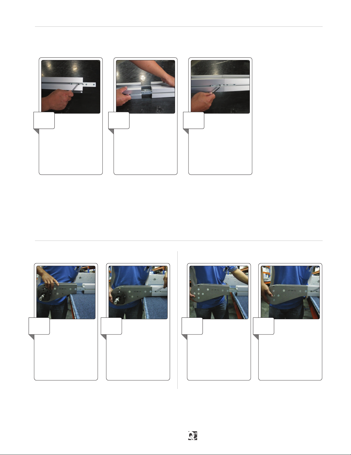
Drive Unit Installation Idler End Installation
End Unit Installation
Conveyor Beam InstallationASSEMBLY
Note: Assemble the entire conveyor beam structure in the same way. If the conveyor beam is too long to mount onto the support struc-
ture in one continuous length, assemble shorter lengths and connect them to each other once fastened to the suport beams.
The next step is to connect the straight sections, drive units, idler units and bends to each other. Connect all conveyor beams
according to instructions below.
Loosen the four set
screws that are inserted
into the drive unit connecting
strips. Insert the connecting strips
into the T-slot of the beam you
want attached to the drive unit.
Make sure the set screws do not
prevent the connecting strips from
sliding into place.
1
Make sure that the set
screws do not prevent
the connection strips
from sliding into place.
2
Insert the idler unit
connecting strips into
the T- slots of the beam end and
tighten it.
1
Connect two conveyor
beam ends by inserting
connecting strips into the
beam T-slots. Use two
connecting strips per beam
joint.
1
Tighten the set screws
using an Allen wrench.
2
Tighten the set screws
using an Allen wrench.
3
Tighten the set screws
using an Allen wrench.
2

8 | Install Slide Rail — Assembly | Flextrac Series
Install Slide Rail ASSEMBLY
Joining Slide Rail
Start the slide rail assembly
at an idler end unit.
Separate the top and bottom
ange of the slide rail at the end of
the rail and press into place.
1
Cut both slide rail ends at
45° angle. The beginning
of the new slide rail section in the
direction of travel should receive
a second cut at a slightly steeper
angle.
1
Ensure the slide rail is
properly mounted and
snaps onto the beam. The anged
edge of the siderail should snap
over the ange on the inner edge
of the beam.
2
Allow a space of
approximately 10mm
between two slide rail ends.
2
Use the slide rail assembly
tool to press the slide rail
into place. One end of the tool is
used when slide rail is mounted
onto rst side of the beam and the
other end is used when mounting
slide rail onto the second side.
3
Do not place two slide rail
joints opposite each other.
Make sure there is a distance of
at least 100mm between them to
make sure the chain run smoothly
(this does not apply at idler end or
drive unit; these joints are always
parallel).
3
Slide rail should be
installed on both top
and bottom of beam (unless top
running chain only).
4
The slide rail is attached to the sides of the conveyor beam to reduce chain friction where the chain would otherwise be in direct
contact with the beam prole. It is very important that the slide rail is installed properly, so that the chain can run without disruption.

qcconveyors.com | Assembly — Wheel Bend Slide Rail Installation | 9
Wheel Bend Slide Rail InstallationASSEMBLY
Try to let the slide rail run in as many continuous lengths as possible, except in circumstances stated below:
• It is recommended to use short slide rail sections (approximately 2m to 3m) where chemicals may have an eect on the slide rail
composition.
• It is important to cut the slide rail and allow for elongation in high load areas. Cuts are required in wheel bends, by idler units and
where the conveyor will be heavily loaded, especially by drive units. This prevents the slide rail from expanding into the drive unit,
which may lock the chain.
• Never join slide rail in plain bends or vertical bends, since forces are higher on the slide rail in these sections. Instead, place the
joint before the bends.
• Avoid joining slide rail on top of conveyor beam joints.
Note: Diagram below shows cross-section of conveyor beam after slide rails are installed for dierent size of frames.
Cut the slide rail end at
45° angle on the inner
radius of the bend.
1Cut the slide rail at 45°
angle with a short back
cut. The slide rail must be longer
than the conveyor beam itself and
there should be a 2mm distance
between the slide rail and the
wheel.
3
The slide rail must be
longer than the conveyor
beam itself and there should be a
10mm gap between the slide rail
and the wheel. Ensure the end
of the slide rail is not bent up or
down.
2On the outer bend, make
sure that the slide rail is
properly connected to the conveyor
beam prole.
4

10 | Fixing Slide Rail Using Rivet — Assembly | Flextrac Series
Fixing Slide Rail Using Rivet ASSEMBLY
Drill two holes near the
beginning of each slide rail
section. Use the drill xture to ensure
clean-cut holes and correct location
of the holes. The holes must be at the
beginning edge of the joint piece, in
the direction of travel, to hold slide
rail in place when conveyor is in use.
Use a well-sharpened drill bit.
1Use a countersink to
deburr and countersink
the holes. Also ensure no metal
lings are left underneath the
slide rail.
2Insert rivets in the holes,
using rivet crimping tools
to crimp the rivets
3Check that rivets do not
protrude over surface
of slide rail. Check both top and
bottom surface of slide rail for
protruding metal.
4
Keep a distance of
approximately 30mm
between rivets and idler unit in
case the idler end must be removed
after conveyor system assembly.
5
Applicable for MS2 and MM3 only
MS2 SR 25 Slide Rail Shown
Tabla de contenidos
Otros manuales de Accesorios de QC Conveyors

QC Conveyors
QC Conveyors AS40-CD Instrucciones de instalación y funcionamiento

QC Conveyors
QC Conveyors PF52 Manual de instrucciones

QC Conveyors
QC Conveyors PF51 Manual de instrucciones

QC Conveyors
QC Conveyors INDUSTRIAL Series Instrucciones de instalación y funcionamiento

QC Conveyors
QC Conveyors PF52 Manual de instrucciones

QC Conveyors
QC Conveyors PF52 Manual de instrucciones

QC Conveyors
QC Conveyors Automation Series Instrucciones de instalación y funcionamiento


