PTC PTC-0110BA-1 Manual de usuario

Publication Number: PTC-0110BA1UM, REV(B) November, 2003
P.T.C. Production & Trading Company AG
UNINTERRUPTIBLE POWER SYSTEM
SINGLE PHASE – 1kW / 2kVA
PTC-0110BA-1
MADE IN THE U.S.A
USER’S MANUAL
P.T.C.
Production & Trading Co. AG
P.O. Box
CH-6330 Cham
Switzerland
Phone: (+41 41) 740 45 54
Fax: (+41 41) 740 46 64
E-Mail: [email protected]
Web: http://www.ptcag.ch

37&3URGXFWLRQ7UDGLQJ&R$* PTC-0110BA1UM, REV(B)
ii
Table of Contents
Page
Safety Instructions .................................................................................................iii
1. General Description.................................................................................................1
1.1 Intended Applications .............................................................................................1
1.2 Functional Overview ...............................................................................................1
2. Setting the Input Voltage Range ............................................................................3
3. Installation Instructions ..........................................................................................3
4. Front Panel Description ..........................................................................................6
4.1 Front Panel: Main Components ............................................................................6
4.2 Front Panel: Indicators and Switches ..................................................................7
5. Rear Panel Description ...........................................................................................8
6. Operation, Controls and Indicators .......................................................................9
6.1 Turning the UPS ON and OFF ................................................................................9
6.2 Visual Indicators ......................................................................................................9
6.2.1 Normal Operation ....................................................................................................9
6.2.2 Standby Mode ..........................................................................................................9
6.2.3 Input AC Failure .....................................................................................................10
6.2.4 Overload Condition ...............................................................................................10
6.2.5 Over Temperature Condition................................................................................10
6.3 Battery Test ............................................................................................................11
7. Taking Care of the Battery....................................................................................11
7.1 Battery Service Life ...............................................................................................11
7.2 Replacing the Battery Pack ..................................................................................12
8. Communications and Remote Control................................................................13
8.1 Dry Contacts Interface ..........................................................................................13
8.1.1 Option 0 (Standard) Dry Contacts Interface .......................................................13
8.1.2 Option 1 Dry Contacts Interface...........................................................................14
8.2 RS-232 Communication Interface ........................................................................15
8.3 Remote ON/OFF Interface…………………………………………………………….15
9. Specifications ........................................................................................................16
List of Figures
Page
Fig. 1 Block Diagram..........................................................................................................2
Fig. 2 Electrical Connections (with Bypass) ...................................................................4
Fig. 3 Electrical Connections (without Bypass)..............................................................5
Fig. 4 Front Panel - Main Components ............................................................................6
Fig. 5 Front Panel - Indicators ..........................................................................................7
Fig. 6 Rear Panel ................................................................................................................8
Fig. 7 Dry Contacts - Option 0.........................................................................................14
Fig. 8 Dry Contacts - Option 1.........................................................................................14
List of Tables
Page
Table 1 Dry Contacts Connector J3 Pin Assignment (Option 0)....................................13
Table 2 Dry Contacts Connector J3 Pin Assignment (Option 1)....................................14
Table 3 RS232 Connector J4 Pin Assignment .................................................................15

37&3URGXFWLRQ7UDGLQJ&R$* PTC-0110BA1UM, REV(B)
iii
IMPORTANT SAFETY INSTRUCTIONS
• The 37&110BA-1 contains an internal high voltage, high energy power source (96VDC battery)
and large high voltage (340VDC) capacitors.
• The unit should not be tampered with by unauthorized personnel !!!
• Turning off the Input ON/OFF Switch and/or disconnecting the input connector do not turn off
the UPS !!!
• The Power Conditioner output is not switched off by the Input ON/OFF Switch !!!
• The unit should only be plugged into an approved double-pole and fused 20A electrical outlet !!!
(for 230VAC input use 15 AMP fuses).
• The Replaceable Battery Pack of the PTC-0110BA-1 (P/N M357380) contains lead-acid batteries.
The Battery Pack should not be opened. It can only be replaced with a new pack (battery cells
cannot be replaced individually).
• Dispose the Battery Pack properly. Careless disposal (such as into a fire) may cause an
explosion. Local regulations may require controlled disposal of lead-acid batteries. Please check
your local regulations before disposal.

37&3URGXFWLRQ7UDGLQJ&R$* PTC-0110BA1UM, REV(B)
1
1. General Description
1.1 Intended Applications
The PTC-0110BA-1 is a high quality, rugged, 1kW / 2KVA, 19” rack-mounted Un-interruptible Power
Source (UPS). In addition to full compliance with all the requirements of MIL-STD-1399 (Section
300), the PTC-0110BA-1 is specifically designed to meet the harsh military shipboard environment.
The high reliability and ruggedness of the PTC-0110BA-1 make it an excellent choice not only for
military shipboard applications, but for critical shore-based applications as well.
1.2 Functional Overview
The PTC-0110BA-1 consists of two main sections: Power Conditioner and UPS (see Fig. 1).
The Power Conditioner is an isolation transformer (with RFI filters and spike absorbers). Both the
input and output of the Power Conditioner are available to the user via the external connectors of
the unit. This configuration allows the user to externally bypass the UPS section of the PTC-0110BA-1
without loosing the surge protection and noise filtering provided by the Power Conditioner. This
capability is extremely important in shipboard applications since most standard commercial
equipment is designed to operate safely from grounded AC lines, whereas in standard shipboard
electrical systems both lines are HOT and none may be grounded. The power conditioner allows
the safe connection of commercial equipment to standard shipboard electrical systems without
creating a safety hazard. See Section 3 for detailed connection diagram. In addition to 115Vac, the
isolation transformer provides a low voltage for the 24Vdc contactor supply. When AC input drops,
the 24Vdc is provided from battery power.
The UPS is composed of a high power factor AC-DC Converter, a Removable Battery Pack, a
Battery Charger, a DC-AC Inverter and a microcontroller-based Control Circuit.
The AC-DC Converter is a high frequency switching converter that provides 320VDC to the DC-AC
inverter. The AC-DC converter draws clean sine input current waveform and does not induce
electrical noise into the input lines.
The Removable Battery Pack contains the energy source used by the UPS to provide power during
AC input failures. The Battery Pack includes eight 12V / 5AH lead-acid, sealed, maintenance-free
type cells. It provides 10 minutes of full rated output power. The Battery Pack is not a serviceable
item. It cannot be disassembled, and can only be replaced as a single unit.
The Battery Charger is a high frequency, voltage-regulated and current-limited DC to DC converter.
It is powered from the 320VDC output of the AC-DC Input Converter and provides temperature-
compensated float charge to the Battery Pack.
The DC-AC Inverter is high frequency inverter that generates clean sine-shape 115VAC voltage
from the 320VDC output of the AC to DC Input Section. The DC-AC Inverter is current-limited and
has an overload protection circuit that turns it off (latched) after a delay from the time the load
exceeds 120%. The delay depends upon the overload level.
The Control Circuit is a microcontroller-based circuit that provides monitoring of the unit’s status
(battery charge, load level, input and output levels, etc.) and supports communications and front
panel status indicators.
Note that when the UPS is bypassed, an external circuit breaker (or fuse) must be used in order to
protect the Power Conditioner from overload. The circuit breaker may be on the input or output
side of the Power Conditioner. The Power Conditioner contains internal fuses on its input. These
internal fuses are intended only as a safety feature in case of an internal failure and should not be
used as overload protection devices.

37&3URGXFWLRQ7UDGLQJ&R$* PTC-0110BA1UM, REV(B)
2
115/220Vac
MANUAL
SELECT
Figure 1: PTC-0110BA-1 Block Diagram
Power Conditioner
RFI FILTER
& VARISTOR
ISOLATION
TRANSFORMER
RFI FILTER
& VARISTOR
AC-DC
CONVERTER DC-AC
INVERTER
CONTROL
&
MONITOR
BATTERY
CHARGER
BATTERY
PACK
24VDC24VRTN
INPUT
ON/OFF
SWITCH
MASTER
ON/OFF
SWITCH
REMOTE
ON/OFF
SWITCH
2 POLES INPUT
CONTACTOR2 POLES OUTPUT
CONTACTOR
J1
AC INPUT
115/230 VAC
EXTERNAL
BYPASS
J1
J2
J2
AC OUTPUT
115VAC
J5
J5
J4 RS-232
J3 DRY
CONTACTS
320 Vdc
120 VDC
115
24 VDC
Low Voltage To
Contactors

37&3URGXFWLRQ7UDGLQJ&R$* PTC-0110BA1UM, REV(B)
3
2. Setting the Input Voltage Range
Note: The input voltage range is set (prior to shipping) to 115VAC.
To change the input voltage range:
a) Turn off both Input and Master ON/OFF switches.
b) Disconnect connectors J1 and J2 from the rear panel.
c) Open the Input Voltage Setting access cover (2 screws).
d) Pull out the exposed connector handle upward.
e) Reconnect the connector in the desired location (the window should line up with the
desired voltage marking).
f) Close the access cover (tighten the two screws).
g) Verify that the desired AC input voltage matches the voltage seen through the window.
3. Installation Instructions
Before installing the unit, please read carefully the Safety Instructions at the beginning of this
manual.
Make sure that the input voltage setting is correct.
Make sure that the Master switch is in the OFF position.
Two circular connectors (J1 and J2) are provided on the rear panel of the UPS (see Figure 6). J1 is
the input connector to the Power Conditioner section of the unit. J2 carries the output of the
Power Conditioner and both input and output of the UPS section. (Please refer to Fig. 1 for the
definitions of the Power Conditioner and the UPS sections.)
Use Figure 2 if it is desired to use the power conditioner as a buffer between the mains and the
load when the PTC-0110BA-1 is externally bypassed.
Please note that grounding of the power conditioner’s output is permitted only at the output side of
the bypass selector (marked as “NEUT” in figure 2).
Use Figure 3 if bypass is not required,.
After the unit is installed and ready to be turned ON, see paragraph 6.1 (Turning the UPS ON and
OFF) for operating instructions.
37&3URGXFWLRQ7UDGLQJ&R$* PTC-0110BA1UM, REV(B)
4
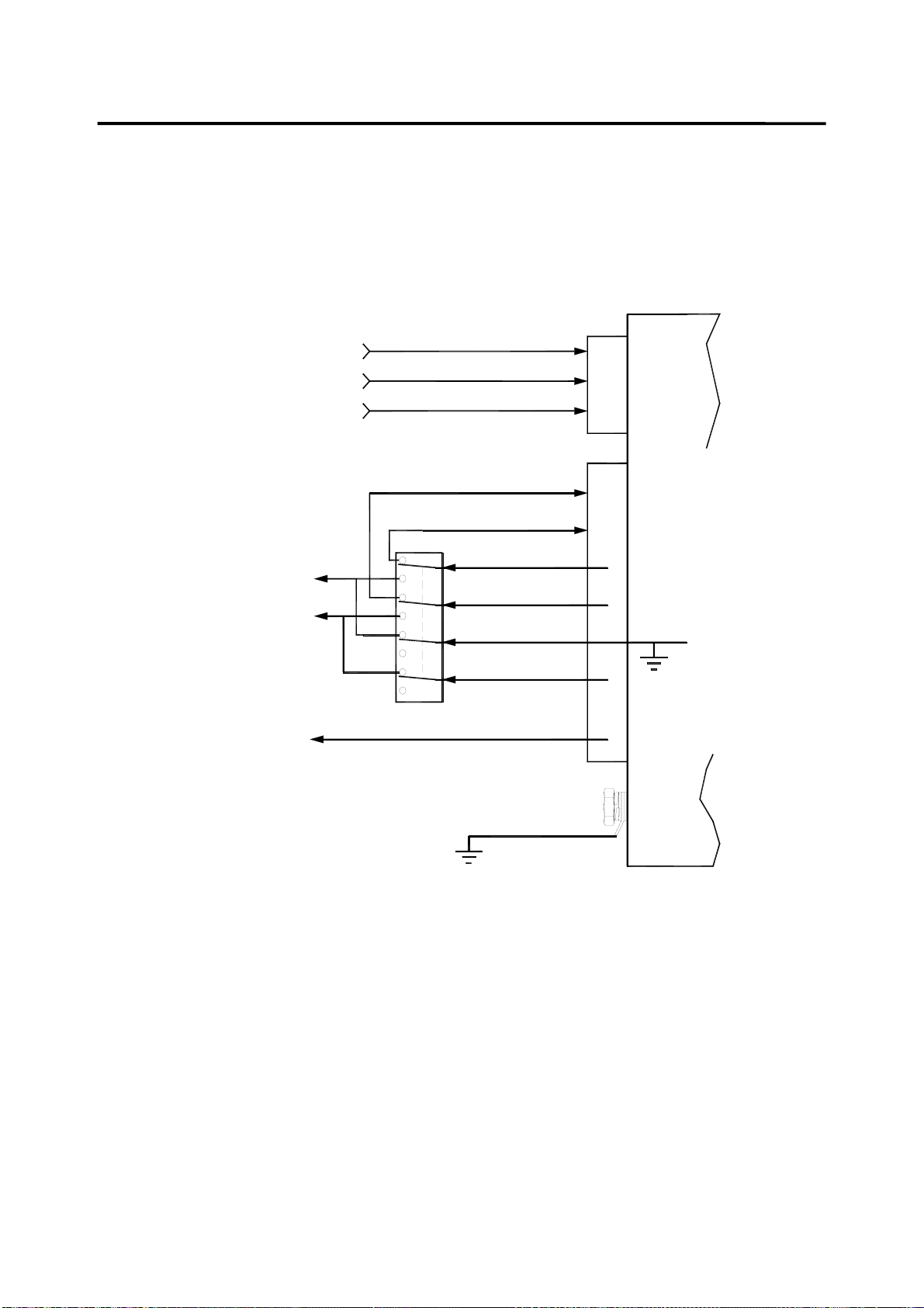
Figure 2 - Electrical Connections (with Bypass)
C
B
A
J1
PWR COND. INPUT PHASE 2
PWR COND. INPUT PHASE 1
CHASSIS GND
UPS IN 2
UPS IN 1
PWR COND. OUT 1
PWR COND. OUT 2
UPS OUT 1 (NEUT)
UPS OUT 2 (HOT)
115VAC
VIA TWO-POLE
CIRCUIT BREAKER
AC TO
LOAD
BYPASS SELECTOR
(NOTE2)
GND
CHASSIS
G
E
C
D
A
B
F
UPS
(NOTE3)
SAFETY GND
REAR PANEL
GND CONN.
NOTES:
1. USE #8 WIRES.
2. POSITIONS OF BYPASS SELECTOR:
UPPER POSITIONS = UPS
LOWER POSITION = BYPASS
3. J2(A) IS INTERNALLY GROUNDED
BY A REMOVAL JUMPER.
NEUT
HOT
20 AMP

37&3URGXFWLRQ7UDGLQJ&R$* PTC-0110BA1UM, REV(B)
5
Figure 3 - Electrical Connections (without Bypass)
C
B
A
J1
PWR COND. INPUT PHASE 2
PWR COND. INPUT PHASE 1
CHASSIS GND
UPS OUT 1 (NEUT)
UPS OUT 2 (HOT)
115VAC
VIA TWO-POLE
CIRCUIT BREAKER
GND
CHASSIS
G
E
C
D
A
B
F
UPS
(NOTE 2)
SAFETY GND
REAR PANEL
GND CONN.
NOTES:
1. USE #8 WIRES.
2. J2(A) IS INTERNALLY GROUNDED
BY A REMOVAL JUMPER.
AC TO
LOAD
20 AMP

37&3URGXFWLRQ7UDGLQJ&R$* PTC-0110BA1UM, REV(B)
6
4. Front Panel Description
4.1 Front Panel: Main Components (See Figure 4)
1. Removable air filter (of the Power Conditioner’s cooling air).
2. Visual Indicators and Switches (for detailed view see Figure 5).
3. Air Inlet (of main UPS heatsink).
4. Input ON/OFF Switch.
5. Master ON/OFF Switch.
Figure 4 - Front Panel: Main Components

37&3URGXFWLRQ7UDGLQJ&R$* PTC-0110BA1UM, REV(B)
7
4.2 Front Panel: Indicators and Switches (See Figure 5)
4. Input ON/OFF switch.
5. Master ON/OFF switch.
6. Input Fail LED (red).
7. Input OK LED (green).
8. Output Standby LED (yellow).
9. Output OK LED (green).
10. Output Fail LED (red).
11. On Battery Warning LED (blinking yellow).
12. Alarm Off Push-button.
13. Low Battery Warning LED (blinking yellow).
14. Overload Shutdown LED (red).
15. Overtemperature Warning LED (blinking yellow).
16. Overtemperature Shutdown LED (red).
17. Load Level Bar Graph (marked in %, 100% = 1000W ).
18. Battery Charge Bar Graph (marked in %., 100% = 10 minutes at 1000W load).
19. Set Battery Charge to 100% Push-button (for maintenance only).
20. Battery Test Passed LED (green).
21. Battery Test Push-button.
22. Battery Test Failed LED (red).
Figure 5 - Front Panel: Indicators and Switches
Tabla de contenidos
Otros manuales de Unión Postal Universal de PTC

Manuales populares de Unión Postal Universal de otras marcas

Pylontech
Pylontech Victron & Pylontech US5000 Manual de usuario

Tecnoware
Tecnoware EVO DSP PLUS MM 6.8 Manual de usuario

Mecer
Mecer ME-1000-WTU Manual de usuario
 Plus Manual de instalación y operación")
Mustek
Mustek PowerMust 530(B) Plus Manual de instalación y operación

Emerson
Emerson Liebert NXL series Manual de usuario

MAKELSAN
MAKELSAN BOXER SERIES Manual de usuario


