Prosense PPS Manager Manual de usuario

2
PRS-UM-PPSM-EN-Rev.03-10.04.2020
WARNING
This user guide must be carefully read by all persons who are or will have the responsibility for
installing, using or servicing this product. This product must be installed, used and serviced in
accordance with the manufacturer's directives. Otherwise it could fail to perform its functions as
designed and persons who rely on this product for their safety could suffer severe personel injury or
death.
Properly installed panel can be used without any problem and covered under Prosense warranty. The
warranties made by Prosense with respect to this product are voided if the product is not installed,
used and serviced in accordance with the instructions in this user manual.
WARNING
Inductive or capacitive loads like motors,ventilation, eg. should not be directly connected to the
panel directly. In such cases, auxiliary external relays should be use to drive these loads.

3
PRS-UM-PPSM-EN-Rev.03-10.04.2020
CONTENTS
1.INTRODUCTION .................................................................................................................................... 4
1.1 Technical Specifications............................................................................................................... 4
1.2 Panel Dimensions .............................................................................................................................. 5
2. INSTALLATION..................................................................................................................................... 5
3. FUNCTIONS AND DETAILS.................................................................................................................... 7
3.1 LCD Screen:........................................................................................................................................ 8
4. MAIN BOARD AND CONNECTIONS...................................................................................................... 9
4.1 Main Board Details:........................................................................................................................... 9
4.2 Backup Battery Connection ............................................................................................................. 10
4.3 Main Power Connection.................................................................................................................. 11
4.4 Detector Connections...................................................................................................................... 11
4.5 PPS Series Detectors Connections................................................................................................... 13
4.5 Relay Outputs .................................................................................................................................. 15
5. FIRST RUN.......................................................................................................................................... 15
5.1 Automatic Test ................................................................................................................................ 16
5.2 LED Test ........................................................................................................................................... 16
6. PROGRAMMING ................................................................................................................................ 16
6.1 Set FAN1 Relay Level: ...................................................................................................................... 16
6.2 Set FAN2 Relay Level: ...................................................................................................................... 17
6.3 Set Alarm Relay Level: ..................................................................................................................... 18
6.4 Set Alarm Activation Type: .............................................................................................................. 18
6.5 Set Gas Type: ................................................................................................................................... 19
6.6 Set Language: .................................................................................................................................. 20
6.7 Scan Detectors:................................................................................................................................ 21
6.8 Show Detector:................................................................................................................................ 21
7. ALARM STATUS.................................................................................................................................. 22
7.1 What to do in case of alarm ............................................................................................................ 22
8. FAULT CODES................................................................................................................................. 23
Declaration ............................................................................................................................................ 24
Warranty Statement.............................................................................................................................. 25

4
PRS-UM-PPSM-EN-Rev.03-10.04.2020
1.INTRODUCTION
Prosense PPS Control Panel is produced specially for carparking area. Prosense PPS control Panel is
able to provide automatic gas concentration reading for gases CO, NO and LPG that mostly exist on
car parking areas. PPS Control Panel permanently transmits the gas concentration measurement
from detectors to the control unit. Before the gas concentration in the atmosphere reaches the LEL
or toxic PPM level, the control panel is able to shut off a gas valve, cut off power and turn on an
alarm via activating relays.
Prosense PPS Control Panel can have up to 4 zone modules that each can monitor up to 32 detectors.
A fully configured PPS Panel can handle managing 128 detectors. PPS Panel can be configured
depending on detectors used in each project with one, two, three or four zone modules.
Prosense PPS Panel has three relays on each zone module those are two level fan relays (F1 and F2)
and one alarm relay. Fan relays are not alarm relays. They will be activated after 60 seconds once the
defined threshold level exceeded and deacticvated after 240 seconds than the alarm status returned
to normal. The PPS Panel has one power module that can provide power to all zone modules. This
power module has also two relays which are fault and alarm. These relays will be activated if any one
of the zone modules generates fault and or alarm status.
Prosense PPS Control panel can manage up to 128 addressable detectors via RS485 serial
communication protocol. PPS Panel has an 2x8 LCD display to adjust measurement and alarm levels.
This LCD screen and menu keys allow user to set correct properties for each detector like gas
concentrations by gas type, measument type, range and alarm levels.
1.1 Technical Specifications
Power Source
220VAC +/-10%
Power Consumption
27VDC/200mA – 5.4W max. (without connected detectors)
Inputs (Internal)
4 x 32 detectors via RS485 serial input
Relay outputs
Fan1, Fan2, Alarm for each zone
Fault and Alarm for overal status
Contacts rating
3A, 24VDC or 3A 120VAC
Display
Graphic LCD (2x8)
LED indicators
Fan1, Fan2, Alarm
Power/ON, Fault, Alarm LEDs
Backup battery
2 x 12V 7A/h (Optional)
Operating Temp.
0-50C
0
Humidity
15-85% non condensing
Housing
ABS IP66 (366 X 276 X 186 mm)
Weight
5,5 kg
Main power fuse
2A
Backup battery fuse
2A
Table 1 : Technical specifications

5
PRS-UM-PPSM-EN-Rev.03-10.04.2020
1.2 Panel Dimensions
Panel dimensions are explained in Diagram 1:
Diagram 1: Dimensions (mm)
2. INSTALLATION
The PPS Control Panel box should never be placed in an explosive atmosphere and should be readily
accessible. It is necessary to drill holes for cable glands either on the top or bottom of the control
unit, depending on which side the electric cables are running in. Before drilling any holes you can
unscrew and remove the electronic parts to avoid accidentally damaging it. PPS Control panel should
not be placed near by high voltage cables or power cable, coaxial cables or transmitters, welding
stations or frequency regulators.
The PPS Control Panel box produced based on IP66 standard specifications. Always use the screw
holes to mount it and do not pierce panel from any other side. Always use cable glands to make cable
entries.
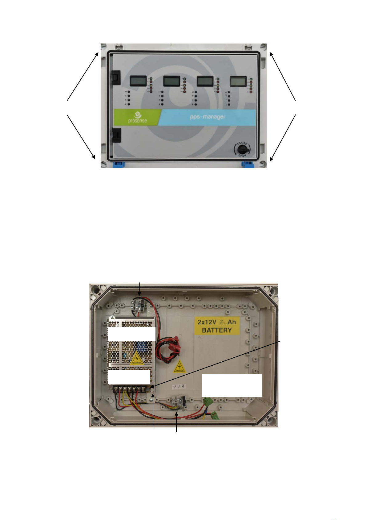
The PPS Control Panel has 4 plastic screws on the front of panel. Use a flat screwdriver to loose them
and remove the cover part on the front. Please take care and remove the connectors on the
electronic card while removing the cover. Fix the panel on the wall via using 4 screw holes after
removing the front cover. Reattached the front cover and tighten 4 plastic screws when wall
mounting completed.

6
PRS-UM-PPSM-EN-Rev.03-10.04.2020
Diagram 2: Panel cover plastic screw
To prepare cable entries, remove plastic covers from top or bottom of the panel. Then drill the holes
for cable entry and install cable glands to the holes you made it. Make sure you are using an
adequate IP66 rate cable gland to assure the box ingress protection is not compromised. The panel
box is modular and can be used with different assemblies. Prosense recommends having cable
entries from the lower side. Electronic board is located in the front cover of the panel. The power
supply is located at the back of panel box. The power must be connected to this power supply. If the
installation requires the connection to a backup battery, place the battery to lover right side of the
panel inside.
Diagram 3: Panel body
Plastic screws
Plastic screws
Backup battery connectors and fuse
Wall mounting hole
Power supply
N L G V-V+
Wall mounting hole
Wall mounting hole
Wall mounting hole
Main power entry and fuse
Space for backup
batteries
Power supply LED
Power supply output
adjustment switch

7
PRS-UM-PPSM-EN-Rev.03-10.04.2020
3. FUNCTIONS AND DETAILS
The front panel has the following LEDs for each zone as shown in Diagram 4:
Sign
Meaning
ON
Panel is in operation
FAN1
FAN1 relay status
FAN2
FAN2 relay status
ALARM
ALARM status
FAULT
Fault condition in at least one of the zone module
Table 2 : Front panel signs and meanings
There are four buttons near by LCD screen to perform configuration and display the detector details.
Their functions are given in table (The key assignments may vary depending on the menu page):
Key
Function For Configuration
Function For Display Operation
Enter to panel configuration
OK - Select key
T
Test button
Return back
↑
Go up
Go to next channel
↓
Go down
Go to next channel
Table 3 : Panel buttons and functions
Diagram 4: Front panel signs LCD and LEDs
There is a front plastic cover to protect panel from outer shells, water and dust. To reach to panel
first you need to open plastic cover via pressing both sides of the latches on the front.

8
PRS-UM-PPSM-EN-Rev.03-10.04.2020
Press to open
Diagram 5: Front cover
If panel ordered with keys a key needed to open plastic cover. In order to make panel connection,
you need to open the front cover using the key at right bottom side of front panel. The key works
clockwise and vice versa.
Diagram 6: Front cover with key
Diagram 7: Locker
3.1 LCD Screen:
PPS Panel has 2x8 LCD display on each zone module to show detector address, measurement level
and range as well as detector gas type.
Sign sample
Meaning
CO
Measured gas type
0
Gas level measured by detector
P
Measurement range (PPM)
D01
Detector address
Table 4 : LCD screen details
If there is no detector connected to channel, LCD screen will show fault status on channel (FLT) and
fault LED will be activated. That channel should be closed (deactivated) via using menu steps.
Locker

9
PRS-UM-PPSM-EN-Rev.03-10.04.2020
4. MAIN BOARD AND CONNECTIONS
4.1 Main Board Details:
PPS Control panel has one power module and main power connection from power supply to control
panel made on this board. This board provides power to zone modules.
Diagram 8: Control panel main board
As shown in the picture, power module has its own fuse. Power module equipped with two relay
modules as fault and alarm. Fault relay will be activated when any of the detector goes in to fault
status and alarm relay will be activated when any of the zone modules raise the alarm status.
Each zone module works independantly with the detectors connected to them. The connection made
by the V+, V-, A and B ports on zone module. Each zone module has three relays which are Alarm,
Fan 1 and Fan 2.
Connections to Zone modules
Fuse
Main power input
Backup
battery input
Fault relay
output
Alarm relay
output

10
PRS-UM-PPSM-EN-Rev.03-10.04.2020
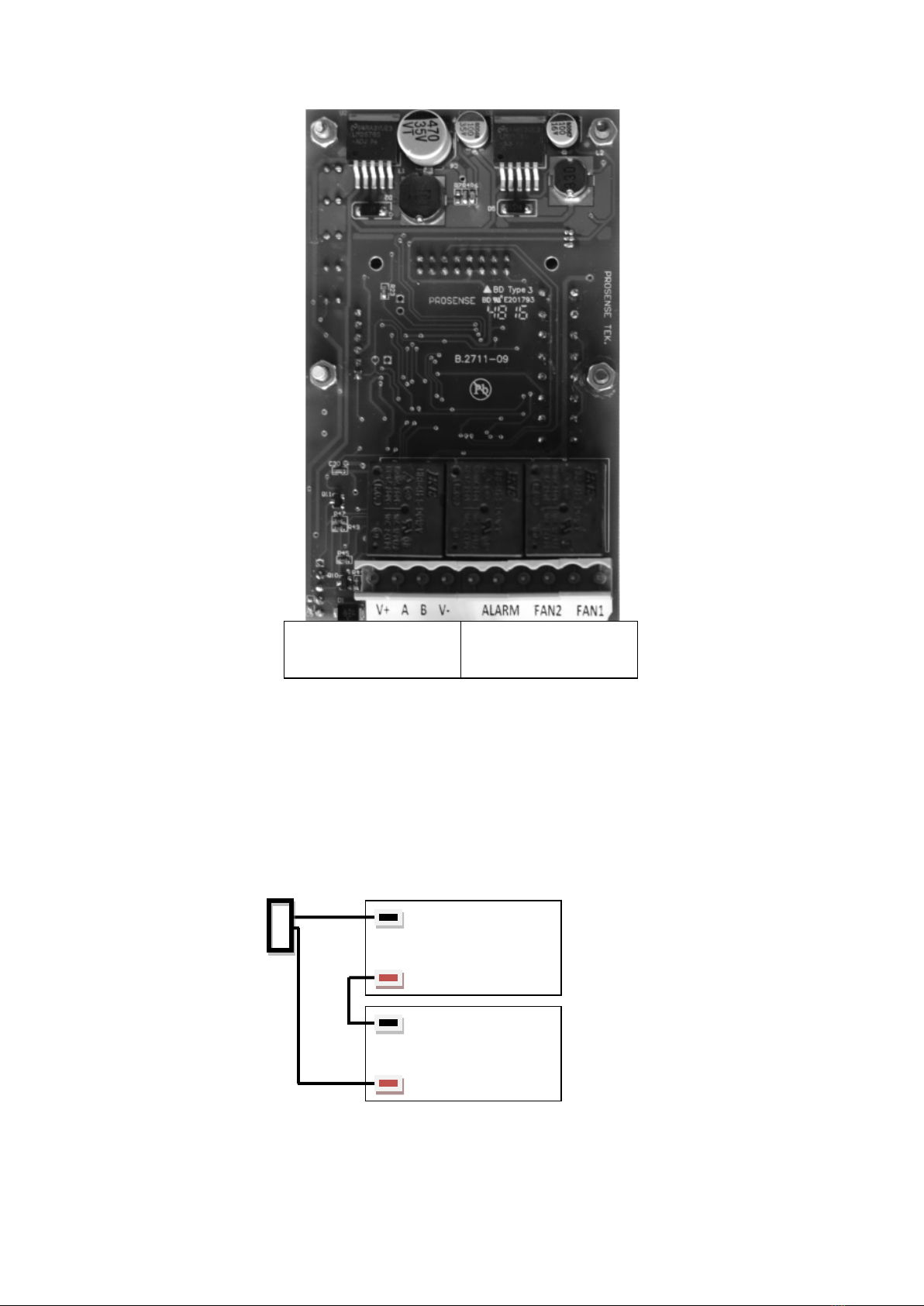
Diagram 9: Control panel zone module board
4.2 Backup Battery Connection
To contiue operation in case of main power failure two backup batteries (12V 7Ah) must be serially
connected to the system. Take extra care to use correct poles while connecting the batteries. The
cables or main board can be damaged in case of mixing pins or making short circuits. Backup
batteries must be connected as shown in Diagram 10 below.
Diagram 10: Backup battery connection
Panel battery input
V+
V-
V+
V-
Battery 1/ 12V 7Ah
Battery 2/ 12V 7Ah
V-
V+
V+ A B V-
Detector connections
Alarm FAN2 FAN1
Relay outputs
Tabla de contenidos
Otros manuales de Panel de control de Prosense