
Prolon T1000 Series Instrucciones de instalación

HARDWARE GUIDE
Digital Sensor - T1000 Series
Specifications and Operational Guide
REV. 6.2.3
PL-HRDW-T1000-F-EN
www.proloncontrols.com |info@proloncontrols.com
17 510, rue Charles, Suite 100, Mirabel, QC, J7J 1X9

2
REV. 6.2.3 / PL-HRDW-T1000-F-EN
Table of Contents
General Information............................................................................................................................ 4
Description ..................................................................................................................................................................... 4
Part Number Selection ................................................................................................................................................ 4
Installation ..........................................................................................................................................5
Power and Communication.................................................................................................................6
Auxiliary Analog Input ................................................................................................................................................ 6
Operation.............................................................................................................................................7
Hint Display .................................................................................................................................................................... 7
Changing the Setpoint ........................................................................................................................ 8
Schedule Override...............................................................................................................................8
Navigating Menus ...............................................................................................................................9
Menu Structure.................................................................................................................................. 10
T1000 Options and Visualisation Menus............................................................................................................... 10
VAV Controller: Visualisation Displays ................................................................................................................... 11
VAV Controller: Configuration Menus (Top Level).............................................................................................. 11
VAV Controller: Configuration Menus - Temperature........................................................................................ 12
VAV Controller: Configuration Menus - Damper................................................................................................. 12
VAV Controller: Configuration Menus - Pressure................................................................................................ 13
VAV Controller: Configuration Menus - Outputs ................................................................................................ 13
VAV Controller: Configuration Menus - Radiant Floor.......................................................................................14
VAV Controller: Configuration Menus - Other.....................................................................................................14
VAV Controller: Configuration Menus - Calibration........................................................................................... 15
VAV Controller: Configuration Menus - Network................................................................................................16
Technical Specifications.................................................................................................................... 17
Compliance ........................................................................................................................................ 18
FCC User Information.................................................................................................................................................18
Industry Canada .........................................................................................................................................................18
Overall Dimensions ........................................................................................................................... 19

3
REV. 6.2.3 / PL-HRDW-T1000-F-EN
Table of Figures
Figure 1 - Opening Tab ..................................................................................................................................................... 5
Figure 2 - Terminal Block Pinout .................................................................................................................................... 5
Figure 3 - Terminal Block.................................................................................................................................................. 6
Figure 5 - Connecting the Auxiliary Input................................................................................................................... 6
Figure 4 - RJ45 Pinout ....................................................................................................................................................... 6
Figure 7 - Touch Pad Feedback....................................................................................................................................... 7
Figure 6 - Touch Pad Controls......................................................................................................................................... 7
Figure 8 - Touch Pad Hint................................................................................................................................................. 7
Figure 9 - T1000 Size Diagram ...................................................................................................................................... 19

4
REV. 6.2.3 / PL-HRDW-T1000-F-EN
Description
The T1000 digital sensors are designed for operation in conjunction with the ProLon VAV or HPS
controllers, to which they provide zone temperature, setpoint and occupancy override information.
The T1000 digital sensors also provide an access point from which to visualize and configure any
parameter on the connected VAV controller through an on-screen menu system.
The T1000 features a circular capacitive touch pad, graphic LCD screen with backlighting and an auxiliary
analog input.
Part Number Selection
General Information
PL-T1000-WGL
Casing Color:
W = White
B = Black
Label Color
GL = Grey Label
WL = White Label

5
REV. 6.2.3 / PL-HRDW-T1000-F-EN
1. Open casing to remove back cover by pushing on the tab located underneath the thermostat.
(Figure 1)
2. Pull wire(s) through central hole of back cover.
3. Screw in the back cover to the wall.
4. Connect wires:
•If using twisted pair wires:
- Pull out the screw terminal blocks.
- Remove 1 cm insulation from the end of each wire.
- Connect the wires to the terminal blocks and re-connect the terminal blocks. (Figure 2)
•If using CAT5 cable:
- Plug the cable into the RJ45 jack of the T1000 (if CAT5 cable is opened at the controller, refer to
Figure 4 for pinout of the T1000's RJ45 jack).
5. Reconnect top cover.
Installation
IMPORTANT: Do not install the thermostat under the following conditions:
•Any location exposed to direct sunlight
•On an outside wall
•Near an air discharge grill
•In a location where vertical air circulation is restricted
•Near a dimmer switch
INT A
INT B
Figure 1 - Opening Tab Figure 2 - Terminal Block Pinout

6
REV. 6.2.3 / PL-HRDW-T1000-F-EN
Power and Communication
The T1000 is typically powered by the same controller it is communicating with. It has two different
connector types available for your choice of preferred wiring method.
• The first is a 4-pin, screw-type terminal block suitable for a 4 wire connection
•The second is an RJ45 connector intended for standard CAT5 cable
Through either of these connection methods, the T1000 is powered (24 VAC Class 2) and communicates
over Modbus RTU (RS485, 57600 bps) as a Modbus Master.
Auxiliary Analog Input
The T1000 has an auxiliary analog input which can be used to connect another thermistor. The T1000 can
be configured to use this alternate temperature reading for a variety of functions, including temperature
averaging or radiant floor slab temperature. The alternate thermistor (10KΩ type 3) can be connected to
the auxiliary input using the “AUX IN” and “COM” pins.
COM
24 VAC
B (-)
A (+)
INT A
INT B
Figure 3 - Terminal Block
Figure 5 - Connecting the Auxiliary Input
Figure 4 - RJ45 Pinout
7
REV. 6.2.3 / PL-HRDW-T1000-F-EN
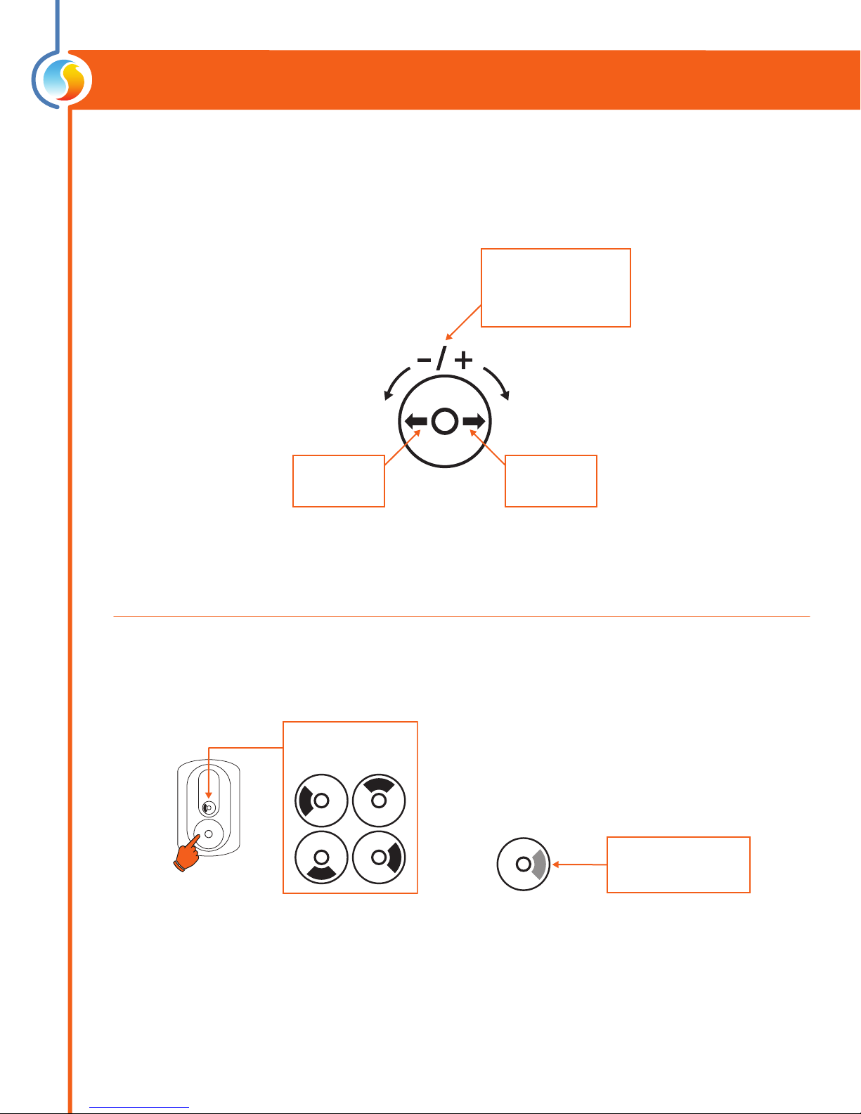
The T1000 is controlled using the circular touch pad on the bottom half of the thermostat. The touch
pad uses capacitive sensing technology to detect finger proximity. There are no moving parts to push or
rotate. The T1000 is controlled using simple scrolling, tapping or holding motions, performed around the
circle of the touch pad. The center of the circle is unused.
Hint Display
At the bottom of the screen, a circle representing the touch pad is displayed, with hints on how to
navigate and modify settings, as well as providing feedback as you manipulate the touch pad. Hints are
context-sensitive and will only display where logical.
Operation
Scroll clockwise or
counterclockwise
to adjust or navigate
Tap here to
ENTER
Tap here to
go BACK
Figure 6 - Touch Pad Controls
Figure 7 - Touch Pad Feedback Figure 8 - Touch Pad Hint
The black arc
follows your nger
Hold your nger over
highlighted areas to use
special features

8
REV. 6.2.3 / PL-HRDW-T1000-F-EN
Changing the Setpoint
Schedule Override
Scroll or tap
(any direction)
Heat SP
Cool SP
Adjust your setpoint
by scrolling clockwise
or counterckwise
View current zone
temperature
Home Screen Setpoint Screen
Tap anywhere
(or simply wait)
return to
Home Screen
The sun icon is
displayed when
overridden
OVERRIDE ACTIVE
(Occupied mode)
The moon icon indicates
unoccupied mode
Scroll clockwise
to override
67.5
79.5
67.5
79.5
First, go to the Setpoint Screen.

9
REV. 6.2.3 / PL-HRDW-T1000-F-EN
Navigating Menus
Menu
75.1
Tap here to
go BACK
SCROLL clockwise or
counterclockwise
to navigate through the
current menu level
Tap here to
ENTER
Active Menu
75.1
Hold left
for 8 sec
Conguration
Menu
Hold right
for 5 sec
Options and
Visualisation Menu
Configure
From the Home Screen.

10
REV. 6.2.3 / PL-HRDW-T1000-F-EN
Menu Structure
The T1000 has two menu systems: The first is dedicated to the general options of the T1000 thermostat
as well as visualization of the status of the controller to which it is connected. The second menu system
is dedicated entirely to the configuration settings of the controller to which it is connected. These menu
structures are outlined below.
T1000 Options and Visualisation Menus
Starting from: T1000
Home Screen
75.1
Hold ‘right’
for 5 sec
Temp Unit
Aux Input
Reset Tstat
Sound
Backlight
Language
Rounding
Type
Software Version
Hardware Version
Status 1
Status 2
Status 3
Device Type
Software Version
Hardware Version
Device #
Device Name
Reset Device
Options
About me
Visualize
Device
Otros manuales para T1000 Series
1
Tabla de contenidos
Otros manuales de Accesorios de Prolon


