Installation
3
2.1.1 Serial Communications Jumpers
Two jumpers, labeled
RxD
and
OUTPUT
, determine
whether the ProÞbus Indicator Interface uses RS-232
or 20 mA current loop for serial communications with
the indicator. Leave the jumpers in the position shown
in Figure 2-4 for RS-232 communications; move both
jumpers to the
20mA
position if using the 20 mA
current loop option. See Figure 2-2 on page 2 for
board location of the jumpers.
Figure 2-3. RxD and OUTPUT Jumpers, Showing Jumper
Positions for RS-232 Communications
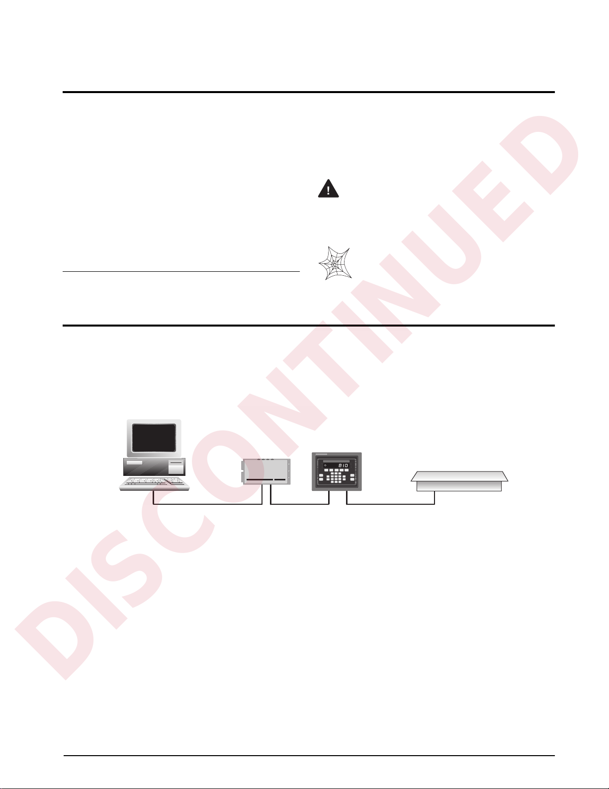
2.1.2 Serial Connections
Serial communications connections to the indicator
are made at connector J5 on the ProÞbus board (see
Figure 2-2 on page 2 for board location of J5).
Figure 2-4 shows the J5 connector layout for the
ProÞbus Indicator Interface. Table 2-1 shows the
serial communications connections between the
ProÞbus Indicator Interface and the IQ plus 800/810
indicators; Table 2-2 shows the serial communications
connections between the ProÞbus Indicator Interface
and the IQ plus 310A indicators.
Figure 2-4. Serial Communications Connections
Table 2-1. IQ plus 800/810 Indicator-to-ProÞbus Serial
Port Pin Assignments
NOTE:
The 20 mA current loop interface connection
requires that the 20 mA option be installed in both the
ProÞbus Indicator Interface and the IQ plus 800/810.
See Section 2.1.5 for information about installing the
20 mA option.
Table 2-2. IQ plus 310A Indicator-to-ProÞbus Serial Port
Connections
2.1.3 Profibus Network Connections
Connections to the ProÞbus network are made at
connector J4 on the ProÞbus board (see Figure 2-2 on
page 2 for board location of J4). Table 2-3 shows the
connections from J4 connector on the ProÞbus board
to the DB-9 ProÞbus connector.
2.1.4 Bus Termination Jumpers
If the ProÞbus Indicator Interface is the last device on
the network bus, install jumpers JMP3 and JMP4 on
the ProÞbus board (see Figure 2-2 on page 2 for
jumper locations).
2.1.5 Installing the 20 mA Current Loop Option
The ProÞbus Indicator Interface can communicate
with IQ plus 800/810 indicators using the 20 mA
current loop interface if the option is installed in both
the Interface and the indicator. Installing the 20 mA
option disables RS-232 communications.
IQ plus 800/810 Indicator Profibus Indicator Interface
Pin Signal Signal J5 Pin
J7-11 RS232/TxD RS232/RxD 8
J7-12 RS232/GND RS232/GND 2
J7-9 RS232/RxD RS232/TxD 3
J7-10 –20mA/TxD –20mA/RxD 8
J7-12 +20mA/TxD +20mA/RxD 7
J7-8 –20mA/RxD –20mA/TxD 6
J7-7 +20mA/RxD +20mA/TxD 5
RxD
20mA
RS-232
OUTPUT
20mA
RS-232
1
J5
Serial Communications
+5V
GND
RS-232 / TxD
CTS
RTS
+20mA OUT
–20mA OUT
+20mA IN
RS-232 / RxD
–20mA IN
IQ plus 310A Indicator Profibus Indicator Interface
Pin Signal Signal J5 Pin
J4-1 RS232/TxD RS232/RxD 8
J4-2 RS232/GND RS232/GND 2
J4-3 RS232/RxD RS232/TxD 3
Profibus
NetworkDB-9
Pin Signal
Profibus
Indicator
Interface J4
Connector Pin
1 Shield ground/Earth ground 10
2
Blank pin
2
3 Profibus B 3
4 RTS 4
5 Power supply common 5
6 +5V 6
7
Blank pin
7
8 Profibus A 8
9
Blank pin
9
NC NC/chassis ground 1
NOTE: If connecting the DB-9 shield ground (pin 1) to J4 pin
10 causes ground loop problems, disconnect.
Table 2-3. ProÞbus Network Connections