
Proeco Bio Flow 5000 Manual de usuario
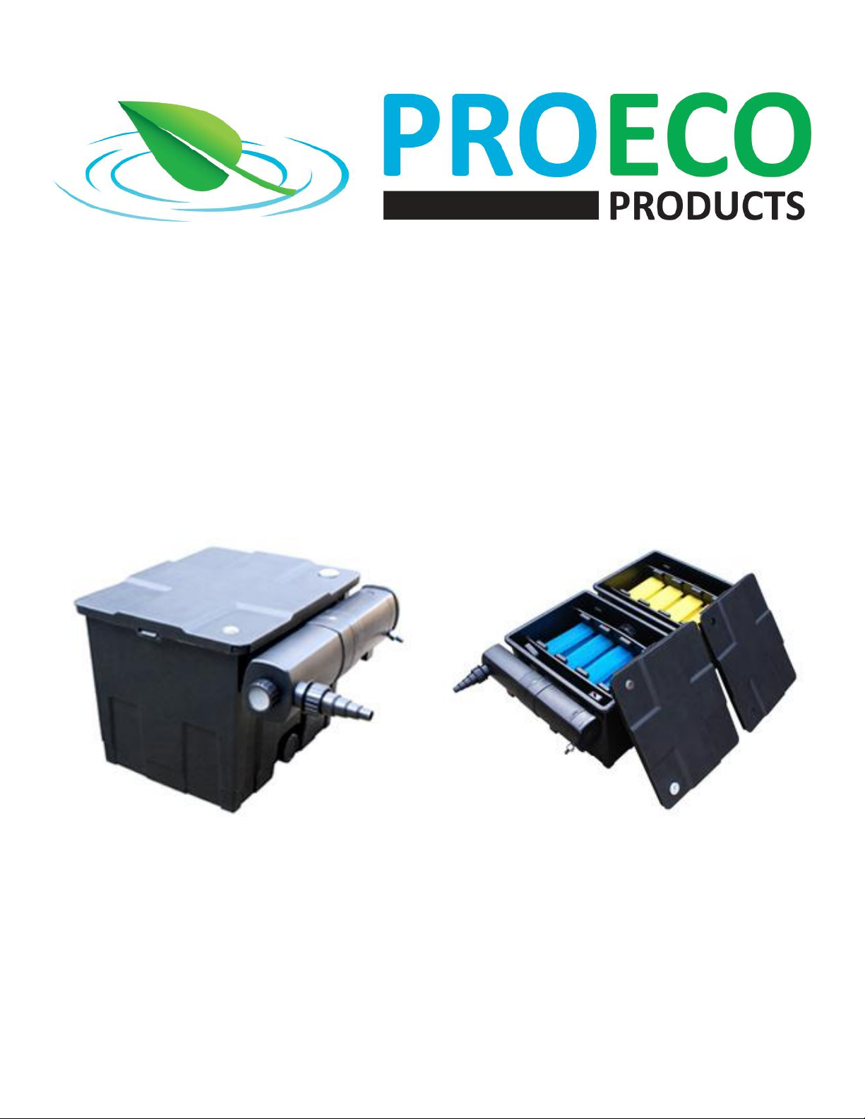
Instrucon Manual
Bio Flow 5000 & 10000
ProEco Products
www.proecoproducts.com
info@proecoproducts.com
Canada (250) 275-4830
United States (503) 922-2254
450 Conn Road
Lumby, BC Canada V0E 2G4
2
Bio Flow Filter Instrucon Manual
INSTALLATION
1. Locate the Bio Flow lter on rm ground and make sure that it is level. Posi-
on the lter so that it can be plumbed eciently and that maintenance can
be done conveniently.
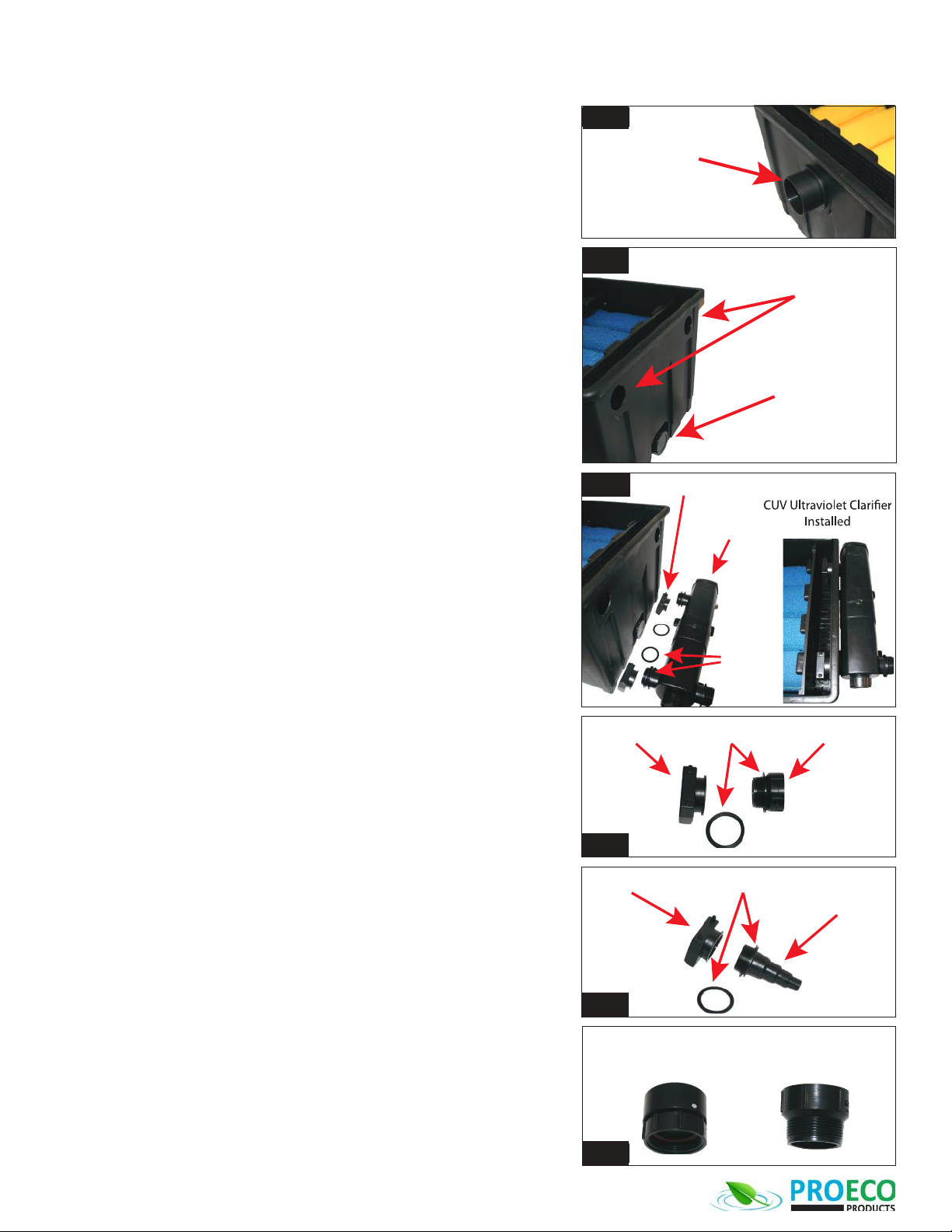
a. Insure that the boom of the Filter Outlet (Fig. 1) is above the water
level of the pond and that the return line will have a minimum slope of
¼” per 1 foot of pipe.
b. Insure that once the unit is installed that there is easy access to the lid,
drain outlet (Fig. 2) and oponal CUV Ultraviolet Clarier (UVC).
2. Install the oponal CUV Ultraviolet Clarier (UVC) (Fig. 3).
a. Install 1 gasket on each of the two outlets of the UVC.
b. Insert the two outlets of the UVC into the Filter Inlet holes (Fig. 2) of
the Bio Flow Filter.
c. Install 1 gasket on each of the two outlets of UVC once they have been
passed through the lter inlets.
d. Aach the venturi ng onto the UVC outlets.
e. Hand ghten the venturi ng so that its outlet is poinng downward
into the lter. It is not necessary to overghten the venturi ng.
3. Install the water supply to the Bio Flow lter. (Choose one of the following
methods based on what kind of hose you will be using and if you will have a
UVC).
a. With a UVC and using Non-Kink Hose.
i. Aach the pipe coming from the pump in the pond to the inlet
of the UVC using the step down hose ng. Cut o any of the
unused poron of the step down ng to insure that you have
the largest diameter opening possible in the ng.
b. With a UVC and using Flexible PVC Pipe.
i. Aach the pipe coming from the pump in the pond to the inlet of
the UVC using a Female PVC adapter ng (Fig. 6).
c. Without a UVC and using Non-Kink Hose.
i. Aach the pipe coming from the pump in the pond to one of the
inlet holes of the Bio Flow lter using the step down hose ng
(Fig. 5). Use two gaskets, one on the outside of the lter and one
on the inside of the lter. Cut o any of the unused poron of
the step down ng to insure that you have the largest diameter
opening possible in the ng.
ii. Install the step down hose ng with the closed end in the
remaining lter inlet. Use two gaskets, one on the outside of the
ng and one on the inside of the ng.
d. Without a UVC and using Flexible PVC Pipe
i. Aach the pipe coming from the pump in the pond to one of the
inlet holes of the Bio Flow lter using a male PVC adapter ng
(Fig. 4). Use two gaskets, one on the outside of the ng and
one on the inside of the ng.
ii. Install the step down hose ng with the closed end in the
remaining lter inlet. Use two gaskets, one on the outside of the
ng and one on the inside of the ng.
4. Install the return line from the Filter Outlet (Fig.1).
a. Insure that the return line has proper slope back to the pond (¼’ per 1
foot of pipe).
5. Check the drain cap to insure that it is ghtened properly and that the gasket
is properly seated in the drain cap.
Filter Inlets
Drain Outlet
Fig. 2
Venturi Fitting Male PVC AdapterGaskets
Fig. 4
Venturi Fitting
UVC
Gaskets
Fig. 3
Step Down
Hose Fitting
Venturi Fitting Gaskets
Fig. 5
Female PVC
Adapter
Male PVC
Adapter
Fig. 6
Filter Outlet
Fig. 1
3
Bio Flow Filter Instrucon Manual
Bio Flow Filter Instrucon Manual
OPERATION
1. Turn on the pond pump.
2. Check that the venturi ngs are channeling the water downward into the
lter.
3. Check that the return water to the pond is owing freely.
4. Check all of the ngs, including the drain cap, to make sure that they are
not leaking.
5. Add benecial bacteria to Bio Flow lter to aid in the bio-ltraon process.
MAINTENANCE AND CLEANING
1. Turn o pump.
2. Remove lid.
3. Remove the drain cap and drain the lter. Several dierent ngs are in-
cluded to facilitate draining of the lter.
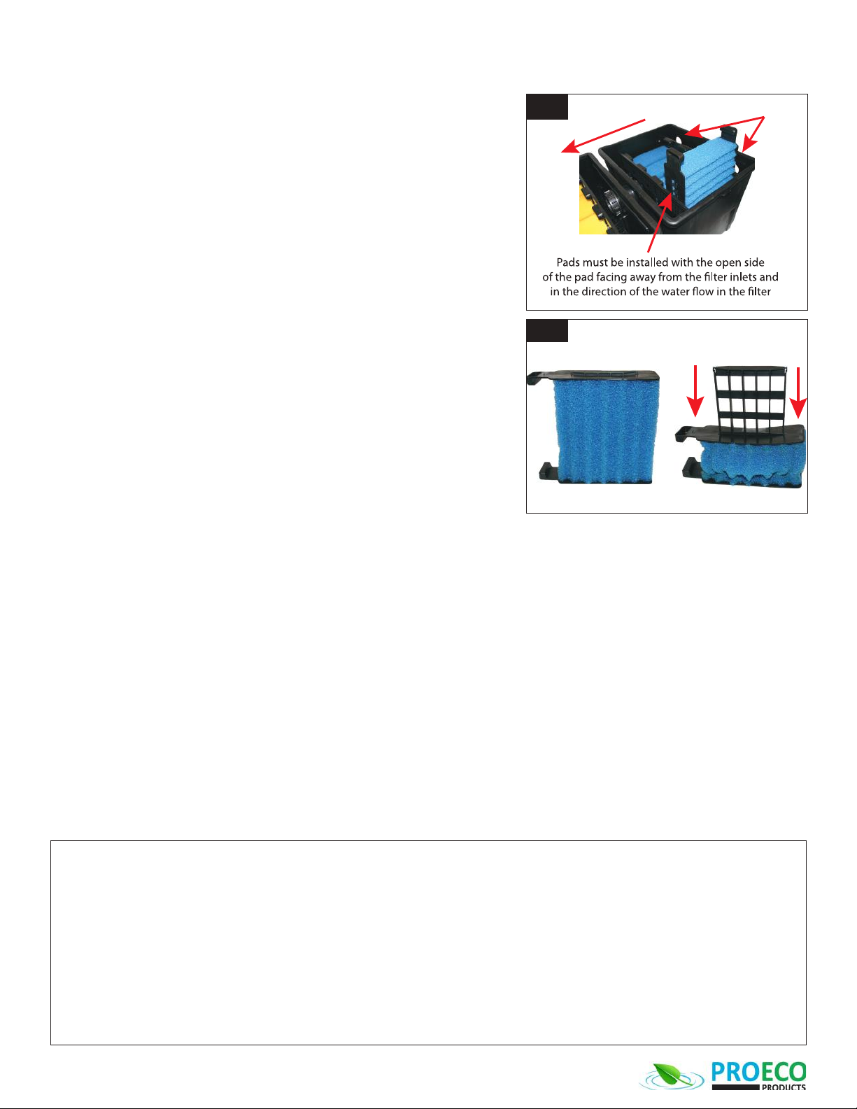
4. Slide out the lter assemblies (Fig. 7).
5. Clean the lter assembly by compressing the foam pad (Fig. 8) and rinsing it
in a bucket of pond water. Using chlorinated tap water can kill the benecial
bacteria.
6. Rinse out the lter housing with a bucket of pond water.
7. Reinstall the lter assemblies in the lter.
IMPORTANT - Make sure that when you are reinstalling the lter assemblies
that the open end of the assembly is facing away from the lter inlets and in
the direcon of the water ow through the lter (Fig.7) . The lter will not
funcon properly if the lter assemblies are installed incorrectly.
8. Replace the drain cap.
9. Turn on pump.
10. Verify that pond water is owing through the lter properly and that there are no leaks.
11. Add benecial bacteria to Bio Flow lter to aid in the bio-ltraon process.
12. Replace lid with the thermometer and cleaning indicator on the lter inlet side.
WINTERIZATION
If you live in a climate that has prolonged periods of temperatures below freezing you can choose to winterize your Bio Flow lter.
1. Turn o pond pump.
2. Remove lid.
3. Remove drain cap and drain the lter.
4. Remove and clean the lter assemblies.
5. Store the lter assemblies indoors submerged in water.
6. Replace lid.
Compress to Clean
Fig. 8
WATER FLOW
Filter Inlets
Fig. 7
Limited Warranty
This PROECO PRODUCTS Bio Flow lter is covered by a 3-year limited warranty by PROECO PRODUCTS. The limited warranty period begins from the date of purchase and covers material and manufacturing defects or
failure of the product to operate as specied by PROECO PRODUCTS during the duraon of the limited warranty period.
This limited warranty does not cover failure or problems related to:
− Improper installaon, see this manual for proper installaon procedures.
− Modicaon of the product in any way including aempts to repair the product by someone other than a PROECO PRODUCTS trained and authorized repair technician.
− Failure to follow proper safety, care and maintenance guidelines as outlined in this manual.
It also does not cover those parts of the product that are subject to normal wear and tear during usage of the product, such as:
− Impellers on pumps
− Filter pads and lter medium in lters
− Lamps in lights and UV clariers
PROECO PRODUCTS's sole liability shall be to replace or repair the product covered by this limited warranty. PROECO PRODUCTS shall not be liable for any consequenal damage to any other part of the water garden,
pond, water feature, landscape, structure, or the contents of any structure where the product is located or used including no liability for damage or harm to sh, animals, or plants in or around the water garden, pond or
water feature.
THE EXPRESS WARRANTIES SET FORTH HEREIN ARE THE ONLY WARRANTIES WITH RESPECT TO THE PRODUCTS, AND THE REMEDIES SET FORTH HEREIN ARE THE EXCLUSIVE REMEDIES IN THE EVENT OF A BREACH OF
SUCH WARRANTIES. PROECO PRODUCTS EXPRESSLY DISCLAIMS ANY IMPLIED WARRANTY OF MERCHANTABILITY OR FITNESS FOR A PARTICULAR PURPOSE. PROECO PRODUCTS SHALL NOT BE LIABLE UNDER ANY
CIRCUMSTANCES FOR INCIDENTAL OR CONSEQUENTIAL DAMAGES OF ANY NATURE, FOR ANY BREACH OF SUCH WARRANTIES OR OTHERWISE. Some states do not allow the exclusion or limitaon of incidental or conse-
quenal damages, to the above limitaon may not apply to you.
Should your PROECO PRODUCTS product be defecve or fail under the terms of this limited warranty, you should return the product to your PROECO PRODUCTS dealer, along with your original receipt of purchase and
any other limited warranty documentaon you have, for replacement or repair. Should you have any queson about this limited warranty, please contact PROECO PRODUCTS at info@proecoproducts.com
Este manual sirve para los siguientes modelos
1
Tabla de contenidos


