Pro Pack Solutions EAGLE T210 Manual de usuario

©Copyright 2012
EAGLE T210
Contents
1. Machine Safety Information 1
2. Machine Installation and Debug 5
3. Machine Operation 9
5. Maintenance and Troubleshooting 12
6. Main Parts, Illustrations and Parts Lists 14
Distributed by:
Pro Pack Solutions, Inc.
P.O. Box 327
Loganville, Georgia 30052
Ph 770-554-1187
www.ProPackSolutions.com

©Copyright 2012
1
1. Machine Safety Information
1.1 Specifications
Specifications
Item EAGLE T210
Power Supply 110V, 60Hz
Carton Size L(6” - ∞) x W(7” – 19.68”) x H(4.7” – 18.9”)
(Fig 1-1)
Max Load 75 lbs
Tape Width 2-3”
Tape Length 1000-2000 yds
Sealing Speed ~30 cartons/minute
Machine Dimensions 38.2” x 35” x 50.3”
Shipping Weight 529 lbs
1.1.1 Sealing Specification of Carton (Fig 1-1)
Fig 1-1
The box range is as follows:
Length is 6” - unlimited
Width is 7” – 19.68”
Height is 4.7” – 18.9”
H
L
W

©Copyright 2012
2
1.1.2 Dimensions of Tape Head (Fig 1-2)
L=16.7”
W=4.25”
H=18.89”
Fig 1-2
1.1.3 The Tab Length (Fig 1-3)
Fig 1-3
Dimension “A” in Fig 1-3 is the adjustable tab length with a range of 2-3”.
1.1.4 Adjusting the Tape Length (Fig 1-4)
Fig 1-4
Move the guiding tape wheel from hole 1 to hole 6 to shorten the tape length.
w
H
L
A
A
©Copyright 2012
3
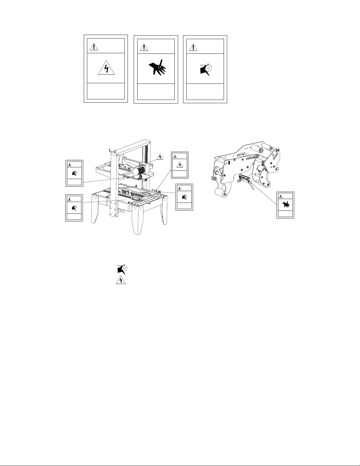
1.2 Safety Caution Symbol
Safety Caution Symbol locations shown in Fig 1-5:
Fig 1-5
Notice: The sign of shows the belt is rotating, keep hands away.
The sign of shows there is motor and electric box, operate the
machine carefully.
1.3 Outline and Application Field
This is an automatic case sealing machine using pressure-sensitive tape such as
PVC and BOPP. It can be set to conform to the shape of the carton and seal boxes
for packaging. This machine has a wide range of applications including the
following fields: chemical fiber field, tobacco leaf drying, pharmaceutical,
publication, refrigeration and air-conditioning, household appliances, ceramics,
etc.
ELECTRIC SHOCK
operate carefully
DANGER
CUT
keep hands away
DANGER
ROLLING
keep hands away
DANGER
DANGER
operate carefully
ELECTRIC SHOCK
DANGER
keep hands away
ROLLING
ROLLING
keep hands away
DANGER
ROLLING
keep hands away
DANGER
DANGER
keep hands away
CUT

©Copyright 2012
4
1.4 Position of Operation (Fig 1-6)
While operating the machine, the employee should stand a minimum of 4” away
from the front of the machine.
Fig 1-6
1.5 Safety Precautions to Operate Machine
1. Verify the power supply for the machine. This machine uses 110V, 60Hz,
single phase power.
2. To avoid cutting fingers, do not touch the blade on the tape head.
3. Do not flush the machine with water.
4. Do not force through or remove cartons while the machine is in operation.
5. Do not put hands on the side conveyors.
1.6 Hearing Safety
1.6.1 Noise: ≤75DB

©Copyright 2012
5
2Machine Installation and Debug
2.1 Installation, Transportation and Storage
2.1.1 Machine Structure and Components Illustration (Fig 2-1)
1. Upright Post Assembly
2. Tape Head Carriage
3. Top Box Squeezer
4. Bottom Conveyor System
5. Electric Box
6. Base Frame
7. Side Guide Rails
8. Tape Head
9. Height Adjustment Handle
Fig 2-1
2.1.2 Installation
Install Upright Post Assembly
(Fig 2-2) Attach upright post assembly to the base frame with screws provided.
(Fig 2-3)
Fig 2-2
Fig 2-3

©Copyright 2012
6
Install Tape Head Carriage
Attach the tape head carriage to the upright post assembly with screws provided.
(Fig 2-4)
Fig 2-4
Install Tape Head
Rest the upper tape head on the carriage placing the notches in the rear of the tape
head onto the supporting shaft. (Fig 2-5) Pull out the draw rod by the key ring,
lower the tape head and release the key ring. For the lower tape head, remove the
front supporting shaft. Rest the rear of the tape head on the rear supporting shaft.
Place the front supporting shaft on the angled notches in the front of the tape head
and lower the tape head down, guiding the pin into the notches in the frame.
(Fig2-6)
Supporting Axle
Fig 2-5
Fig 2-6

©Copyright 2012
7
Install Table Extensions
Align the holes in the extension with the posts in the frame and carefully lower the
table extension. (Fig 2-7)
Screw Hole
Fig 2-7
2.1.3 Transportation
Transport by lift truck (Fig 2-8)
Fig 2-8
2.1.4 Operation environment conditions
It should be far from smoke, dry and ventilated. Humidity≤98%
Normal environment temperature should be within 32-104° F.
No special requirements for electromagnetic radiation.
2.2 Debug
2.2.1 Check Prior to Operation
1. Make sure all nuts and bolts are properly fastened.
2. Make sure the motor and electrical equipment are dry and well insulated.

©Copyright 2012
8
3. Make sure the external power is correct for the power supply of the machine.
2.2.2 Empty Operation
1. Turn on power; after 2-5 minutes verify the machine is operating normally.
2. Rotate the width adjustment handle by hand to assure that the movement of the
side conveyor system is easy.
3. Rotate the height adjustment handle by hand to assure that the movement of
the tape carriage is easy.
4. Make sure the belt is properly positioned.
5. Adjust the tightness of the belt.
6. Check that the tape is properly loaded on the tape head and that the action is
smooth when dispensing tape.

©Copyright 2012
9
3 Machine Operation
3.1 Functions of Control Panel (Fig 3-1)
1. Power Indicator
2. Start Button
3. Emergency Stop Button
Fig 3-1
3.2 Feeding the Adhesive Tape (Fig 3-2)
Fig 3-2
3.3 Operation Steps
1. Plug in the machine, turn Power Switch to the on position, twist emergency stop
button to the right until it pops up if it was depressed.
2. Press start button, manually push the case through, the belt will drive it and seal
automatically.
3.4 Daily Maintenance
Proper maintenance to the case sealer prolongs the life of the machine and helps to
avoid problems that would affect the machines production efficiency.
3.4.1 Lubrication
The sealing speed of this machine is very fast. Therefore the machine parts should
be lubricated often.
3
2
1
ADHESIVE
Emergency stop
button
Tabla de contenidos


