Prisma 2.0 Guía

TECHNICAL DOCUMENTATION
THERMOSIPHONIC SOLAR
WATER HEATERS
Thank you for placing your trust in our products. Our solar systems have been designed and
manufactured according to the strictest quality standards so that they may offer many years of top of
the range performance. For any clarifications regarding our products or this manual you may contact
one of our dealers, visit our website www.calpak.gr or contact us directly.

THE MOSIPHONIC SOLA WATE HEATE S / TECHNICAL DOCUMENTATION / JANUA Y 2021 PAGE 1
TABLE OF CONTENTS
I. INTRODUCTION PAGE 2
II. TECHNICAL CHARACTERISTICS PAGE 4
III. POSITIONING OF THE SYSTEM PAGE 7
IV. INSTALLATION OF SYSTEM ON A FLAT ROOF [Singl coll ctor syst ms] PAGE 8
V. INSTALLATION OF SYSTEM ON A FLAT ROOF [Twin coll ctor syst ms] PAGE 16
VI. INSTALLATION OF SYSTEM ON INCLINED ROOF [All syst ms] PAGE 19
VII. HYDRAULIC CONNECTION OF SYSTEM [All syst ms] PAGE 26
VIII. ELECTRICAL CONNECTIONS PAGE 34
IX. INSTALLATION OF COLLECTOR ARRAYS UP TO 20m² PAGE 35
X. FUNCTION AND MAINTENANCE PAGE 36
XI. DECOMMISSIONING PAGE36

THE MOSIPHONIC SOLA WATE HEATE S / TECHNICAL DOCUMENTATION / JANUA Y 2021 PAGE 2
I. INTRODUCTION
SAFETY MEASURES
Always use certified installation tools and full protection devices.
In case you need to work near electrical wires, turn the electricity off.
Always wear protective goggles, protective boots, gloves and masks in compliance with the
respective safety regulations.
TRANSPORT & HANDLING
The tanks and the collectors come packed in expanded polystyrene frames and stretch films, where
they must remain during all transportation and storage. The collectors must be transported in vertical
position, in order to avoid any damage. During installation keep the collector covered until the closed
circuit is filled with thermal fluid.
LIGHTING PROTECTION
Connect the metal part of the collector with the lighting protection system, if available or otherwise
connect them to an earth rod. For further information consult a specialist.
Thermal effects due to lightning currents are considered negligible (Annex E, paragraph E 5.10 standard
EN 12976-2).
The mechanical loads on the components of the solar system due to lightning charges are too low and
the effect on durability and stability is considered negligible (Annex E, paragraph E 5.11 standard EN
12976-2).
The solar thermal system can be connected to the existing lightning protection at the roof of a building,
in order to be protected against any form of damage due to lightning. Additionally, please note that the
solar system is a natural circulation system and its electrical resistance is fed from the main building
switchboard, provided that there is always possibility of connecting the electrical resistance of the
storage tank to the building’s central earth. The electrical resistance is tested according to standards
EN 60335-1 and EN 60335-2-21.
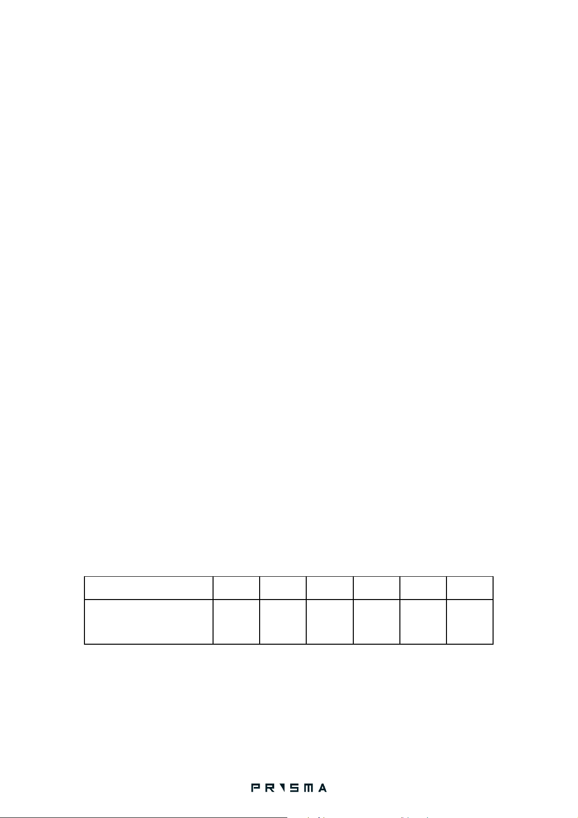
THERMAL FLUID
It is a propylene glycol based thermal fluid, non-toxic to the skin. It must be used diluted in water in
order to provide anti-freezing and anti-corrosive properties. The advisable percentage is 33% of water
volume. In case of very low environmental temperatures, increase the volume percentage according to
the following table:
Temperature (ºC) -10 -15 -20 -25 -30 -35
Percentage in water solution
(%) 23 31 37 43 48 53
PERMISSIBLE SNOW LOAD AND MEAN WIND VELOCITY
The collectors are tested according to the standards EN 12975-2. Through these tests, it is admitted
that they can resist without any failure to a mechanical load up to 2400 Pa.

THE MOSIPHONIC SOLA WATE HEATE S / TECHNICAL DOCUMENTATION / JANUA Y 2021 PAGE 3
SYSTEM COMPONENTS
1. Collector
2. Tank
3. Support Base System
4. Thermal fluid (propylene glycol)
5. 1 pressure relief valve for the closed circuit
6. 1 safety valve for the domestic cold water line
7. Insulated connecting pipes
8. Pipe fittings
SYSTEM IDENTIFICATION
The tank and the collector/s which form a solar system are appropriately marked with metalized item
plates. These plates include the technical characteristics of the system and the unit serial number
according to paragraph 4.7 of EN 12976-1 and are placed on each part of the system (tank and
collector/s)

THE MOSIPHONIC SOLA WATE HEATE S / TECHNICAL DOCUMENTATION / JANUA Y 2021 PAGE 4
II) TECHNICAL CHARACTERISTICS
Technical data
P ISMA flat plate selective collectors
Type
Prisma 2.0 Prisma 2.5
Gross area (m²) 2.00 m
2
2.50 m
2
Absorber area (m²) 1.90 m
2
2.37 m
2
Aperture area (m²) 1.91 m
2
2.39 m
2
W x L x H (mm) 1235x1625x85 1235x2020x85
Weight (kg) 29.15 35,4
Absorber capacity (l) 1,38 1,55
Housing Pre-painted and galvanized steel
Absorber Selective aluminum
Absorption 95+1
Emission (%) 5
Number of tubes 8
Absorber tube Dia. 8 mm
Glass 3.2 mm low iron mistlite tempered glass
Transmittance of glass (%) >0,91
Insulation 30 mm glasswool
Stagnation temp at 1000
W/m²and 30C 180 C
Max. operating pressure
(bar) 10

THE MOSIPHONIC SOLA WATE HEATE S / TECHNICAL DOCUMENTATION / JANUA Y 2021 PAGE 5
Coll ctor
Aluminum flat plate selective absorber
Ultrasonic welded on copper harp
ock wool insulation
Single piece pre-painted zinc coated alloy-steel (ArcelorMittal) casing
Colofast ® by BASF® reinforced collector body corners
Low iron tempered glass
Tank
Enameled tank according to DIN 4753/3
Insulation with expanded polyurethane, 50mm thick
Magnesium anode cathodic protection according to DIN 4753/6
Electrical resistance 3,5 KW
Heat exchanger to connect to a boiler (model T IEN)
Bas
Heavy duty galvanized steel
Optimized construction
CNC production for superior accuracy and quality
Unified system for all systems for ease of installation
Superior anchoring to roof

THE MOSIPHONIC SOLA WATE HEATE S / TECHNICAL DOCUMENTATION / JANUA Y 2021 PAGE 6
Model 160/2 160/2.5 200/2.5 200/ 4 300/ 4 300/ 5
Dim nsions
[45 d gr
inclination]
Width
(mm)
Α 1314 1314 1680 2594 2594 2594
Length
(mm)
Β 1624 1903 1903 1624 1624 1903
Height
(mm)
C 1731 2010 2010 1731 1731 2010
System weight empty (kg)
87.15 93.4 108.4 131.3 154.3 166.8
System weight full (kg) 239.5 245.9 299.9 324.1 433.1 445.9
Optional electrical
resistance (kW) 3,5 3,5 3,5 3,5 3,5 3,5
Tanks
Tank volume
(l) 151 151 190 190 276 276
Tank weight
empty (kg) 58 58 73 73 96 96
Tank weight
full (kg) 209 209 263 263 372 372
Length (mm)
1230 1230 1520 1520 1980 1980
Diameter
(mm) Ø 500
Coll ctors
Dimensions
of collector
(mm)
1235x1625
x85
1235x2020
x85
1235x2020
x85
1235x1625x
85
1235x1625x
85 1235x2020
x85
Number of
collectors 1 1 1 2 2 2
Gross area
per collector
(m²)
2.00 2.50 2.50 2.00 2.00 2.50
Weight per
collector
empty (kg)
29.15 35.4 35.4 29.15 29.15 35.4
Max.
working
temp. 180ºC
Thermal
liquid per
absorber (l)
1.38 1.55 1.55 1.38 1.38 1.55
Max.
collector
circuit
working
pressure
2bar

THE MOSIPHONIC SOLA WATE HEATE S / TECHNICAL DOCUMENTATION / JANUA Y 2021 PAGE 7
IΙI) POSITIONING OF THE SYSTEM
The installation area of the solar water heater must fulfill the following requirements:
1.1 The solar water heater must fac th SOUTH (or NORTH in cas th installation tak s plac in th
South h misph r ), and it is strongly recommended to use a compass to ensure this. Deviations of up
to 10-15does not affect substantially the system’s efficiency, but larger deviations may seriously affect
the performance.
1.2 In countries situated in latitude of 40, the collectors must be installed at an angle of 45against
the horizontal level. The collectors must be generally placed at an angle of 5over the latitude of the
installation area. Any decrease in this angle entails considerable decrease of the solar heater’s annual
performance.
1.3 In no case are the solar heaters to be placed in the shade, especially during winter time, when the
sun is lower in the sky. The minimum distance between the solar heater and any obstacle that causes
shadow should be no less than twice the height of the obstacle.

THE MOSIPHONIC SOLA WATE HEATE S / TECHNICAL DOCUMENTATION / JANUA Y 2021 PAGE 8
IV) INSTALLATION OF SYSTEM ON A FLAT ROOF [All singl coll ctor mod ls]
The Prisma base system has been pre-assembled so as to maximise ease of use and safety. Check that
the subassemblies are as shown in the figures below and make sure that you use the correct
subassembly for each step.
Figur 2: Prisma system preassembled components, from top to bottom: Pillar assemblies, collector
diagonals. Note the differences between right and left variants.

THE MOSIPHONIC SOLA WATE HEATE S / TECHNICAL DOCUMENTATION / JANUA Y 2021 PAGE 9
STEP 1
Identify the area where the system will be installed according to the guidelines in page 7.
Identify South and install the two pillars as shown above. In the southern hemisphere point to the
North.
The distance between the two holes should be 1090 mm.
Make sure that the two pillars are parallel and alighned.
Note position of right and left pillar.
Fixing hardware [shown in gray] is not provided with the system, the installer must ensure that the
hardware is appropriate for given roof material. Diameter of bolts should be 8mm, length and type
according to roof.
ATTENTION: Failure to fix the pillars to the roof material will eventually result in support structure
failure under extreme loading conditions.
In order to avoid humidity problems or water penetration (rain/snow) in the roof, the pipes which are
entering the roof must be very well sealed. Local building engineer should provide you with precise
guidelines depending on the kind of roof construction and/or local legislation. The same applies to the
system anchoring points, regardless of the devices used for the installation.
Este manual sirve para los siguientes modelos
7
Tabla de contenidos


