PSR5042 User Manual
REV1.0 7
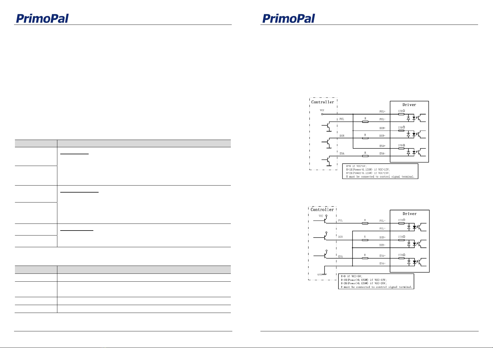
5.3.2 Parallel Connections
An 8-lead motor in a parallel configuration offers a more stable, but lower torque at lower
speed. But because of the lower inductance, there will be higher torque at higher speed.
Multiply per phase (or unipolar) current rating by 1.96, or the bipolar current rating by 1.4, to
determine the peak output current.
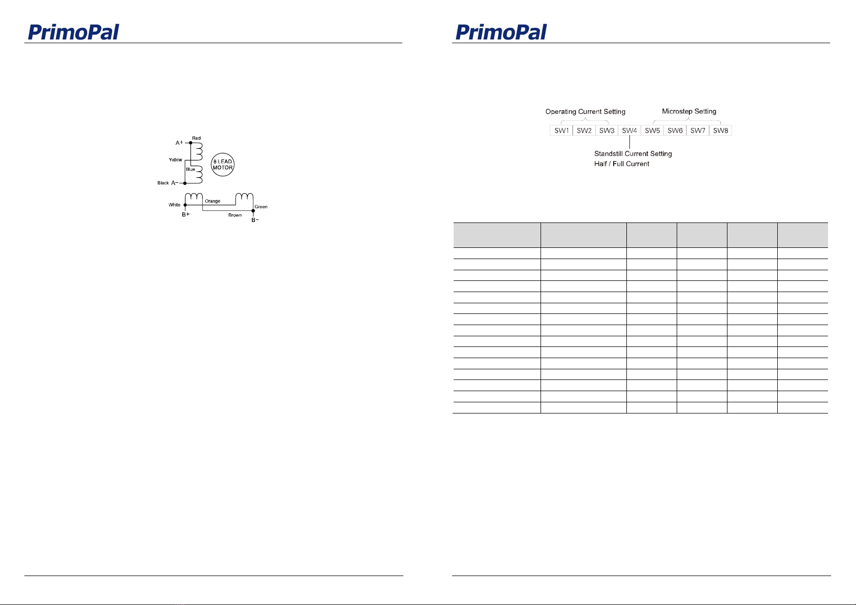
Figure 8: 8-lead motor parallel connections
6. Power Supply Selection
The stepper drive PSR5042 can match medium and small size stepping motors (from NEMA
size 17 to 24). To achieve good driving performances, it is important to select supply voltage
and output current properly. Generally speaking, supply voltage determines the high speed
performance of the motor, while output current determines the output torque of the driven
motor (particularly at lower speed). Higher supply voltage will allow higher motor speed to be
achieved, at the price of more noise and heating. If the motion speed requirement is low, it’s
better to use lower supply voltage to decrease noise, heating and improve reliability.
6.1 Multiple Drives
It is recommended to have multiple drives to share one power supply to reduce cost, if the
supply has enough capacity. To avoid cross interference, DO NOT daisy-chain the power
supply input pins of the drives. (Instead, please connect them to power supply separately.)
6.2 Selecting Supply Voltage
The power MOSFETS inside the stepper drive PSR5042 can actually operate within +18V~
+50VDC, including power input fluctuation and back EMF voltage generated by motor coils
during motor shaft deceleration. Higher supply voltage can increase motor torque at higher
speeds, thus helpful for avoiding losing steps. However, higher voltage may cause bigger
motor vibration at lower speed, and it may also cause over-voltage protection or even drive
damage. Therefore, it is suggested to choose only sufficiently high supply voltage for
intended applications, and it is suggested to use power supplies with theoretical output
voltage of +24~+ 45V, leaving room for power fluctuation and back-EMF.
PSR5042 User Manual
REV1.0 8
7. Selecting Microstep Resolution and Drive Output Current
This drive uses an 8-bit DIP switch to set microstep resolution, and motor operating current,
as shown below:
7.1 Microstep Resolution Selection
Microstep resolution is set by SW5, 6, 7, 8 of the DIP switch as shown in the following table:
Microstep Steps/rev.
(for 1.8°motor) SW5 SW6 SW7 SW8
2 400 OFF ON ON ON
4 800 ON OFF ON ON
8 1,600 OFF OFF ON ON
16 3,200 ON ON OFF ON
32 6,400 OFF ON OFF ON
64 12,800 ON OFF OFF ON
128 25,600 OFF OFF OFF ON
5 1,000 ON ON ON OFF
10 2,000 OFF ON ON OFF
20 4,000 ON OFF ON OFF
25 5,000 OFF OFF ON OFF
40 8,000 ON ON OFF OFF
50 10,000 OFF ON OFF OFF
100 20,000 ON OFF OFF OFF
125 25,000 OFF OFF OFF OFF
7.2 Current Settings
For a given motor, higher drive current will make the motor to output more torque, but at the
same time causes more heating in the motor and drive. Therefore, output current is generally
set to be such that the motor will not overheat for long time operation. Since parallel and
serial connections of motor coils will significantly change resulting inductance and resistance,
it is therefore important to set drive output current depending on motor phase current, motor
leads and connection methods. Phase current rating supplied by motor manufacturer is
important in selecting drive current. However, the selection also depends on leads and
connections.