INTEL PII
User’s Guide
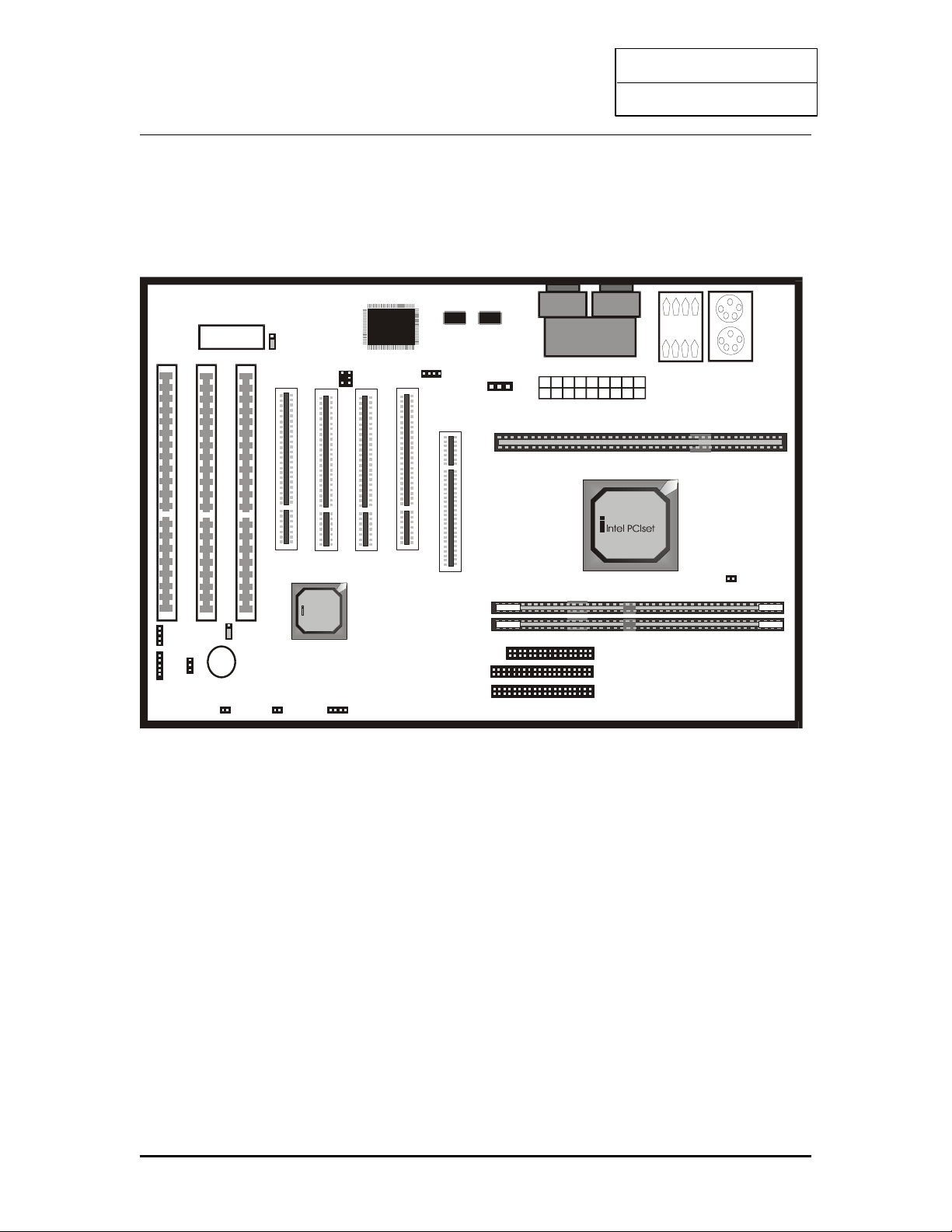
1. INTRODUCTION
YEAR2000 COMPLIANCE
This Intel chipset mainboard is Hardware Year2000 Compliance and supports the latest Pentium
III Processor. It achieves the highest performance which based on the advanced Pentium II
Microprocessor and featuring PCI ocal Bus and Accelerated Graphics Port feature. This
mainboard offers a high degree of flexibility in configuration and is fully IBM PC/AT
compatible.
1.1 KEY FEATURES
This manual applies to different models of Intel chipset mainboard. Please refer to appropriate
section and mainboard layout according to the model no.
Model No. T -BX31 T -ZX31 T -BX21 T -ZX21
Chipset i440BX i440ZX i440BX i440ZX
Socket Slot 1
Front-Side Bus 66 / 100 MHz
Processor INTE Pentium III 450 MHz or above Processor (Please download the updated
BIOS from our website)
INTE Pentium II 233 – 450 MHz Processor
INTE Celeron / Celeron A 266 MHz or above Processor
CPU Speed Jumperless setting
oltage Regulator Built in switching voltage regulator to support 1.5V to 3.5V
Cache Built in evel 2 cache: 512KB (PII and PIII), 128KB (Celeron A)
SDRAM Support 66MHz and 100MHz (PC100) SDRAM module. Also SPD or Non SPD.
Each DIMM slot supports up to 256 MB.
168 pin DIMM
Slot
3 2 3 2
Max. System
Memory
768 MB 512 MB 768 MB 512 MB
Expansion Slots 1 x AGP 1.0 slot (1X/2X mode)
4 x PCI slots
3 x ISA slots
1 x AGP 1.0 slot (1X/2X mode)
3 x PCI slots
2 x ISA slots
On-borad I/O 2 x Ultra DMA/33 Bus Master IDE Ports (support up to 4 IDE devices and PIO
Mode 3 & 4, DMA 2 & Ultra DMA 33)
Support HD greater than 8.4GB
1 x Floppy port (up to 2.88 MB floppy)
1 x Serial ports (16550 Fast UART)
1 x Parallet port (ECP/EPP)
2 x USB ports
1 x PS/2 mouse port
1 x Infra-red port
System BIOS Award 1M or 2M Flash BIOS
Support ACPI, DMI, PnP, Green, Wake on Modem (external) features
Wake on LAN Yes -- --
Power Connector ATX ATX and AT
Sound on Board -- -- Crystal Sound (4235)
1