PFT G 5 c FU Manual de usuario

PFT G 5 c FU 230V Operating Manual Issued: 09.2007
Knauf PFT GmbH & Co. KG
1
OPERATING MANUAL
(Item number of operating manual: 00 11 01 43)
(Item number of machine – parts list: 00 02 08 05)
Mixer Pump
PFT G 5 c FU 230V
WE KEEP THINGS MOVING

PFT G 5 c FU 230V Operating Manual Issued: 09.2007
Knauf PFT GmbH & Co. KG
2
Contents
Contents 2
Dear PFT customer 4
Proper use of the machine 5
Description of functions 5
Overview of G 5 c FU: Item number 00 02 08 05 6
Overview of control box G 5 c FU: Item number 00 07 04 97 7
Overview of air manifold: Item number 00 03 96 13 8
Overview of water manifold: Item number 00 04 91 76 – 1000 ltr. 9
Basic safety instructions 11
Basic safety instructions 12
Signs 14
Technical Specifications 16
Settings 17
Mortar pump D6-2L 18
Start-up 19
Measures at the end of work and when cleaning 24
Clearing hose blockages 26
Measures to be taken in the event of a power failure 26
Measures to be taken in the event of a water supply failure 27
Measures to be taken if there is a risk of frost 27
Transport 28
Maintenance 28
Accessories 29
Fault – Cause – Remedy 30
Spare parts diagram of material hopper and frame 32
Spare parts list for material hopper and frame 33
Spare parts diagram of mixing tube and geared motor 34
Spare parts list for mixing tube and geared motor 35
Spare parts diagram of mortar pump / mortar pressure gauge 36
Spare parts list for mortar pump / mortar pressure gauge 37
Spare parts diagram of control box: Item no. 00 07 04 97 38
Spare parts list for control box: Item number 00 07 04 97 39
Spare parts diagram of control box: Item number 00 07 04 97 40
Spare parts list for control box: Item number 00 07 04 97 41
Spare parts diagram of water manifold: Item number 00 04 91 76 42
Spare parts list for water manifold: Item number 00 04 91 76 43
Spare parts diagram of booster pump: Item number 00 05 24 76 44
Spare parts list for booster pump: Item number 00 05 24 76 45

PFT G 5 c FU 230V Operating Manual Issued: 09.2007
Knauf PFT GmbH & Co. KG
3
Spare parts diagram of air compressor DT 4.16: Item number 00 07 64 44 46
Spare parts list for air compressor DT 4.16: Item number 00 07 64 44 47
Spare parts diagram of air manifold: Item number 00 03 96 13 48
Spare parts list for air manifold: Item number 00 03 96 13 49
Circuit diagram 50
Circuit diagram 51
Parameter settings for the Yaskawa type 606 V7 frequency converter 52

PFT G 5 c FU 230V Operating Manual Issued: 09.2007
Knauf PFT GmbH & Co. KG
4
Dear PFT customer
Congratulations on your purchase. You have made a wise choice as you clearly value the quality
that comes with a brand name product from a reputable company.
The PFT G 5 c FU mixer pump uses state-of-the-art technology. It was functionally designed to be
a reliable aid under rough construction site conditions.
This operating manual should always be stored and kept at hand at the site where the machine is
used. It contains information on the various functions of the machine. Study the operating manual
thoroughly before starting the machine, as we accept no liability for accidents or damage to the
machine caused by incorrect operation.
The PFT G 5 c FU mixer pump will prove to be a trustworthy aid providing it is operated correctly
and handled with care.
It is prohibited to forward this document, even excerpts, without our written authorisation. All
technical specifications, diagrams etc. are subject to copyright law. All rights, errors and
modifications are reserved.
Initial inspection after delivery:
An important task of all technicians delivering the PFT G 5 c FU is the inspection of the machine
settings at the end of the first work phase. The factory settings may change during the initial cycle.
If these changes are not corrected in time, immediately after run-in, problems may arise during
operation.
Following receipt of the PFT G 5 c FU mixer pump and training in regard to it, i.e. after about two
hours of operation, the technician must always carry out the following checks / make the following
settings:
1) Water pressure switch
2) Pump pressure, backpressure
3) Air pressure switch
4) Pressure reducer
It is prohibited to forward this document, even excerpts, without our written authorisation. All technical
specifications, diagrams etc. are subject to copyright law. All rights, errors and modifications are reserved.
© by Knauf PFT GmbH & Co. KG

PFT G 5 c FU 230V Operating Manual Issued: 09.2007
Knauf PFT GmbH & Co. KG
5
Proper use of the machine
The PFT G 5 c FU is a continuously operating mixing pump for pre-mixed machinable mortar with
a particle size of up to 2 mm.
Please observe the processing guidelines of the material manufacturer!
The machine consists of portable individual components of handy dimensions that allow fast,
convenient transport.
The following points should be observed during operation:
1) Connection for worksite distribution board – control box
2) Connection for control box – pump motor
3) Connection for control box – compressor
4) Connection for compressor – air manifold
5) Connection for water supply – water manifold / booster pump
6) Connection for air manifold – air hose
7) Connection for air hose – finishing plaster device
8) Connection for mixing tube – mortar pressure gauge
9) Connection for mortar pressure gauge – mortar hose
10) Connection for mortar hose – finishing plaster device
Description of functions
The PFT G 5 c FU can be loaded with bagged materials or by means of a delivery hood or injection
hood. The mixing shaft and the pump are driven by a geared motor. The pump motor speed is
approximately 400 rpm. Water is added and mixed into the dry material in the mixing area. The water
flow rate needs to be set manually at the needle valve. The water flow rate may be checked using the
water flow meter. A pressure switch monitors the water flow pressure. If it falls below 1.9 bar, the
machine shuts down automatically. This problem is prevented by installing a booster pump upstream.
The mixed mortar is pumped away by a screw pump installed downstream from the mixing shaft.
A spraying gun can be mounted at the end of the conveying hose. The compressed air required for
spraying is supplied by a compressor.

PFT G 5 c FU 230V Operating Manual Issued: 09.2007
Knauf PFT GmbH & Co. KG
6
Overview of G 5 c FU: Item number 00 02 08 05
1. Mixer pump motor 9. Pump system D6-2L
2. Star wheel 10.Water supply to mixing tube
3. Protective grille with bag opener 11.Control box
4. Material hopper 12.Mixing tube with exchangeable flange
5. Air compressor DT 4.16 13.Locking lever
6. Star wheel gearbox 14.Motor tilt flange
7. Booster pump Pkm 60 15.Pump motor connection cable
8. Water manifold
PFT G 5 c FU 230V Operating Manual Issued: 09.2007
Knauf PFT GmbH & Co. KG
7
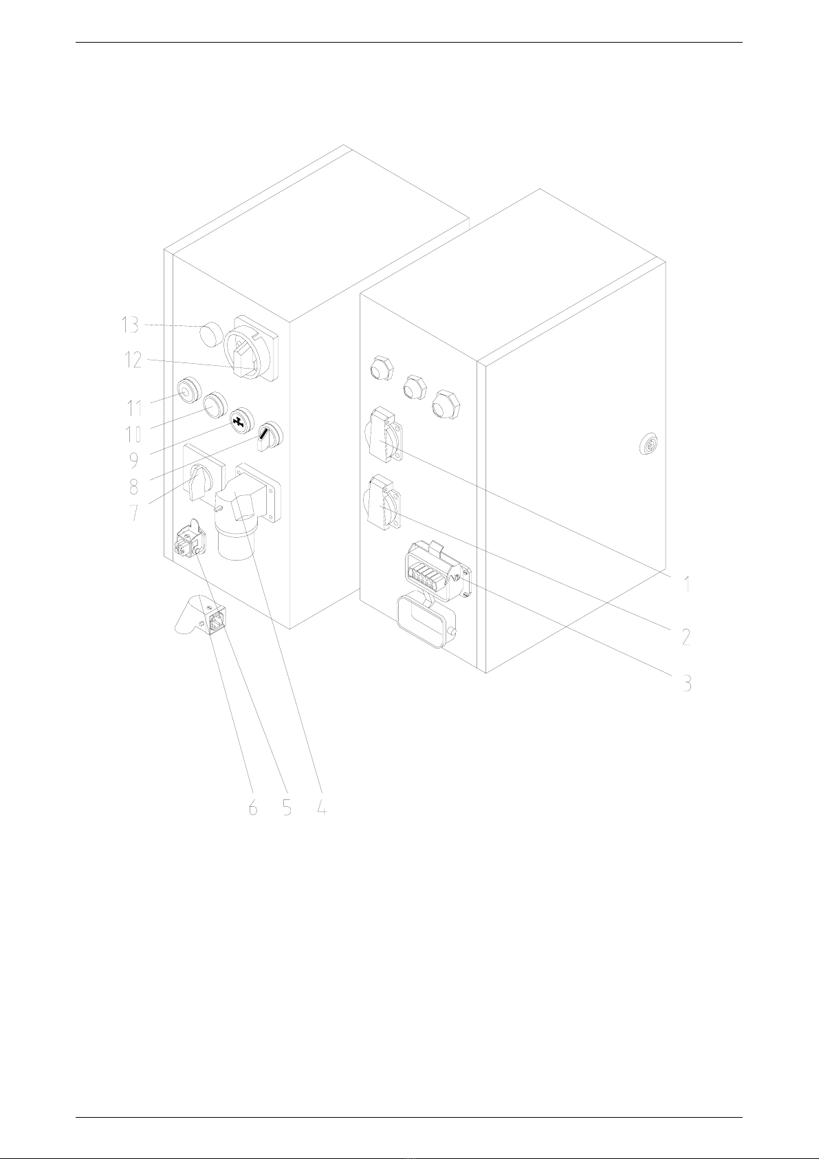
Overview of control box G 5 c FU: Item number 00 07 04 97
1. Socket compressor 230 V, 16 A 8. Mixer motor direction of rotation
2. Socket for booster pump 230 V, 16 A 9. Water flow button
3. Housing (10-pin), mixer motor 10.Operation ON
4. Main power supply CEE 3 x 16 A 11.Operation OFF
5. Remote control socket 42 V 12.Main switch
6. Dummy plug for remote control socket 13.Control lamp fault
7. Star wheel selector switch 14.

PFT G 5 c FU 230V Operating Manual Issued: 09.2007
Knauf PFT GmbH & Co. KG
8
Overview of air manifold: Item number 00 03 96 13
1. Air from compressor 4. Air to spraying gun
2. Compressor shutdown device 5. Check valve, 1/2" female thread
3. Air pressure safety switch 6.

PFT G 5 c FU 230V Operating Manual Issued: 09.2007
Knauf PFT GmbH & Co. KG
9
Overview of water manifold: Item number 00 04 91 76 – 1000 ltr.
1. Solenoid valve 7. Manometer 0 – 4 bar
2. Pressure reducing valve
(regulation of water pressure)
3. Pressure switch 1.9 – 2.2 bar
8. Manometer 0 – 16 bar
9. Outlet tap (draining of water manifold if
there is risk of freezing)
4. Water outlet (open – closed) 10. Needle valve (regulation of water quantity)
5. Water outlet 11. Water flow meter
6. Water from booster pump 12. Water to mixing tube

PFT G 5 c FU 230V Operating Manual Issued: 09.2007
Knauf PFT GmbH & Co. KG
10
Dangers and warning symbols
The following terms and symbols are used in this manual for particularly important information:
In order to make the operation of our machines as easy as possible for you, we would like to briefly
inform you of the most important safety instructions. If you comply with these instructions, you will
be able to use our machine in a safe and quality-assuring manner for a long time to come.
Warning – hot surface!
Proper handling:
Hot surfaces should not be touched without protective gloves.
Waste oil!
Proper handling:
Only pour waste oil in the disposal container if it consists purely of oil.
(Do not pour in any mixtures, such as mixed benzine and oil!)
Warning – dangerous area!
Proper handling:
Observe the danger warning and exercise the appropriate caution
(e.g. protective clothing) and prudence.
Warning – dangerously high voltage!
Proper handling:
In work areas with this designation, work may be performed only by those
persons who possess the required expertise (e.g. electricians or persons with
authorisation for electrical work) and who have been assigned this work by the
contractor.
Unauthorised individuals may not enter such designated work areas or open
cabinets with this designation.
Tabla de contenidos
Otros manuales de Mezclador de PFT

PFT
PFT CAYMAN Manual de usuario

PFT
PFT HM 24 Manual de usuario

PFT
PFT HM 2002 Manual de operación

PFT
PFT MULTIMIX Guía

PFT
PFT ZP 3 XL MIX Manual de usuario

PFT
PFT LOTUS XL light Series Manual de usuario

PFT
PFT MULTIMIX Manual de usuario

PFT
PFT HM 2002 Manual de usuario

PFT
PFT MULTIMIX ZP 3 L Manual de usuario


