PEDROLLO VSP Manual de usuario

PEDROLLO S.p.A.
Via E. Fermi, 7 37047 – San Bonifacio (VR) - Italy
Tel. +39 045 6136311 – Fax +39 045 7614663
MADE IN ITALY
VSP
INVERTER ON BOARD FOR ELECTRIC PUMP
CONTROL
EN Correct disposal of WEEE (DIRECTIVE 2012/19/EU)
code 12039901Q01 00/22


1
VSP |
TABLE OF CONTENTS
GENERAL INFORMATION .................................................................................................................................................... 2
SAFETY RULES..................................................................................................................................................................... 2
SYMBOLS............................................................................................................................................................................ 2
WARNINGS ......................................................................................................................................................................... 3
PRODUCT DESCRIPTION ..................................................................................................................................................... 4
TECHNICAL DATA................................................................................................................................................................. 4
POWER AND ABSORPTION.................................................................................................................................................. 4
USE LIMITATIONS................................................................................................................................................................ 5
AUTO-LIMITATION FOR OVERLOAD...................................................................................................................................... 5
PARTS LIST.......................................................................................................................................................................... 5
THE CONTROLS ................................................................................................................................................................... 5
DISPLAY SYMBOLS.............................................................................................................................................................. 6
INSTALLATION..................................................................................................................................................................... 6
PRESSURE SENSOR ............................................................................................................................................................. 7
ELECTRICAL CONNECTION ................................................................................................................................................... 8
CONNECTIONS DIAGRAM..................................................................................................................................................... 8
POWER SUPPLYTERMINAL BOARD...................................................................................................................................... 9
INPUTS/OUTPUTS TERMINAL BOARD................................................................................................................................... 9
PUMPS CONNECTION IN PARALLEL.................................................................................................................................... 11
START-UP........................................................................................................................................................................... 11
PUMP PRIMING ................................................................................................................................................................ 11
FUNCTIONING PARAMETERS ............................................................................................................................................. 12
ADVANCED PARAMETERS MENU ....................................................................................................................................... 14
ALARMS............................................................................................................................................................................. 21
TROUBLESHOOTING.......................................................................................................................................................... 23
MAINTENANCE ................................................................................................................................................................. 26
DISPOSAL........................................................................................................................................................................... 26
DECLARATION OF CONFORMITY....................................................................................................................................... 26

2| VSP
GENERAL INFORMATION
• This manual must always accompany the equipment to which it refers and be kept in an accessible place to be consulted
by those involved in system operation and maintenance.
• Installers/users must read the instructions and information in this manual carefully before using the equipment in order
to avoid damaging or misusing it, or voiding the warranty.
• This product must not be used by children or people with reduced physical, sensory or mental capabilities, nor those with
inadequate experience and knowledge, except under supervision and instruction. Children should be observed to make
sure they do not play with the equipment.
• The manufacturer shall not be held liable in the event of an accident or damage due to negligence or failure to follow the
instructions described in this booklet or in conditions other than those specied on the rating plate. The manufacturer
shall not be held liable for damage due to improper use of the equipment.
• Inspect the goods immediately on receipt to make sure that the equipment has not been damaged during transport. If
faults are found, you are advised to provide prompt communication, not over 5 days from receipt to our retailer or, in the
event of direct purchase, to Pedrollo Customer Service.
• The indications and instructions in this manual refer to standard use of the product; for situations, functions or particular
applications not described below, contact the retailer.
• If a request for technical support or spare parts are necessary, specify the code of the model and the serial number out-
lined in the specic plate.
• Our service department and technical support is available for any requirements you may have.
• Do not stack weights or other boxes on the package.
• The information contained in the manual can vary without prior warning. Any damage caused in relation to
these instructions will not be considered since they are approximate. Remember that non-compliance with
the instructions outlined by us could cause harm to people or property.
• However, remember that compliance with local provisions and/or legislation in force should be met.
SAFETY RULES
SYMBOLS
The symbols used in this manual are described below.
RISK OF ELECTRIC SHOCK
This symbols warns that failure to observe the instructions will create a risk of electric shock.
RISK OF DAMAGE TO PEOPLE OR PROPERTY
This symbols warns that failure to observe the instructions will create a risk of personal harm or property damage.

3
VSP |
WARNINGS
• Please read all parts of this manual carefully before installing and using the product.
• Check that the rating plate data is as required and matches the facilities.
• Only qualied personnel capable of making electrical connections in accordance with national regulations may carry out
installation and maintenance.
• TheVSP must only be used for the purpose and operation for which it was designed. Any other application and use should
be considered misuse and hazardous.
• In the event of a re at or near the installation site, do not use water jets, but use suitable extinguishers (powder, foam,
carbon dioxide).
• Install the equipment away from heat sources in a dry, covered place in accordance with the specied degree of protection
(IP).
• Only qualied technicians who are aware of the safety regulations in force may carry out any installation and/or mainte-
nance work.
• Use of non-original spare parts, tampering or improper use will void the product warranty.
• The manufacturer cannot be held liable for damage deriving from misuse of the product and is not responsible for damage
caused by maintenance or repairs carried out by unqualied people and/or using non-original spare parts.
DURING THE FIRST INSTALLATION PHASE AND IN THE EVENT OF MAINTENANCE, ensure that:
• THERE IS NO LIVEVOLTAGE on the electricity mains.
• The system IS NOT PRESSURISED
• The electrical power mains is equipped with safety devices and, in particular, a high sensitivity dierential switch (30
mA in class F and B) suitable to protect against fault currents, alternating type, unipolar button, continuous with high
frequency. Also check that the earthing complies with the regulations.
• Before removing the cover of the inverter or starting interventions on it, disconnect the system from the electrical mains
at least 5 minutes so that the capacitors have the time to discharge using the built-in discharge capacitors;
• Having carried out the electrical connection on the system, check the settings of the inverter.
• Do not remove the cover and/or disconnect theVSP power if the inverter is running.
ATTENTION: If out of services (display on in OFF with white background) VSP remains live; before any
intervention, it is compulsory to disconnect power from the unit.
EMERGENCY STOP
WhileVSP is running, you can make an emergency stop by disconnecting the power supply to the unit.
Ensure there is no VOLTAGE on the electricity mains. Make sure that the system is NOT PRESSURISED.

4| VSP
PRODUCT DESCRIPTION
VSP is a speed regulator with the following characteristics.
• It receives mono-phase or three-phase alternating voltage.
• It supplies alternating three-phase output voltage.
• Check motor on 3 phases.
• Variable speed adjustment (inverter)
• Keeps system pressure constant (curves with variable rotations).
• Checks hydraulic and electrical operating parameters and protects the electric pump from faults.
• It is equipped with an expansion board, which allows working parallel with other inverters in the pumping unit and
management of an input and an output signal.
• It adapts to every type of pressurisation system, even existing.
• It limits the peak and operating currents, with energy saving.
• It allows selection of the supply and output voltage.
• Maximum current electronic control for overload (adjustable)
• Protection against over or under voltages
• Electronic control for dry run (cos φ adjustable)
• Automatic reset from dry run with cycle times separately programmable from 0÷120 minutes
• Alarm output (NC-C-NO resistive load - 5A / 250V)
TECHNICAL DATA
Power supply voltage 230±10%V mono-phase or 400±10% V three-phase
Output voltage 230V three-phase or 400 V three-phase
Frequency 50-60 Hz
IP protection rating IP 55
Ambient temperature -5 °C / +40 °C
Relative humidity 50% to 40 °C
ATTENTION: in the presence of low voltage (rated value -10%) overcurrents can occur in start-up and at max-
imum power.
POWER AND ABSORPTION
Model V in V out I out P2 max (kW) P2 max (HP)
VSP mono-phase 1 ~ 230V 3 ~ 230V 7 A 1.1 1.5
VSP three-phase 3 ~ 400V 3 ~ 400V 6 A 2.2 3.0

5
VSP |
USE LIMITATIONS
• Maximum working pressure: 9 bar (130 p.s.i). (check with other models)
• Fluids permitted: clean and chemically non-aggressive liquid water; if impurities are found in the liquid, install a lter
upstream.
• Maximum ambient temperature: 40°C, with the possibility of changing the air.
• Minimum ambient temperature: -5°C
• Maximum temperature of the liquid: 55°C
• Minimum temperature of the liquid: 0°C
• Variation in voltage supply permitted ±10% compared to plate data.
• VSP is not suitable for pumping ammable liquids or working in environments with danger of explosion.
AUTO-LIMITATION FOR OVERLOAD
If the current detected by the inverter or the temperature of the inverter components exceeds the safety limits,VSP proceeds
with a progressive reduction in operating frequency until the values exceeding the limits have returned within them.
PARTS LIST
1. INVERTER
2. Electric pump
3. Control panel
4. Cable glands
THE CONTROLS
5. Display with 4 backlighting modes
– Green: inverter/electric pump running
– White: inverter/electric pump in stop or in stand-by
– Yellow: inverter/electric pump in programming (setup)
– Red: inverter/electric pump in alarm mode
6. Scroll arrow keys
7. ESC menu output key
8. ON/OFF key
9. OK key
4
2
31
STOP
6
789
5

6| VSP
DISPLAY SYMBOLS
10. ALARM signalling indicator light
11. AUTOMATIC operating indicator light
12. MANUAL operating indicator light
13. Electric pump no. 1 running indicator light
14. Electric pump no. 2 running indicator light (if present)
15. ActiveWI-FI signalling indicator light (if present)
16. Two-line alphanumeric display showing voltage, frequency, current, cosφ,
pressure, level, system operating state and system faults.
17. VSP operating status led indicator light
INSTALLATION
Incorrect installation can cause malfunctioning and breakage of the VSP.
The VSP must be installed in compliance with the following conditions.
• In a ventilated room, protected from the weather and not exposed to sunlight.
• On a solid horizontal base with screws.
• Do not install theVSP in explosive environments or in the presence of dust, acid, gas that are corrosive and/or ammable.
TYPICAL INSTALLATIONS
NO!
NO!
YES NO!
NO!
YES
VSP-MKVSP-PLURIJET
1 1
4
2 2
4
3 3
46
5
4 4
VSP-FCR
STOP
15
16 12
13 11
14
10
17

7
VSP |
NO!
YES
VSP-PLURIJET VSP-MK
12
4
3
3
4
COMPONENTS LEGEND
1. Pressure Sensor
2. Expansion tank
3. Shut-o valve
4. Check valve
5. Filter grate
6. Bottom lter with grate
POSITIONING OF THE PRODUCT
• Fasten the unit to a horizontal surface with screws.
• If the pump must be installed outside where frost can occur, protect it to avoid freezing.
For correct operation of the VSP, installation is indispensable of an adequate expansion tank
.
• The expansion tank:
– Accumulates pressurised water to reduce pump start-up to a minimum.
– It is indispensable in the presence of small system leaks.
– It absorbs any excess pressure from the system.
–The minimum volume necessary, in litres (for membrane models) is approximately equal to 10% of the maximum ow
rate of the individual pump, expressed in l/min.
Example of standard application: Qmax = 80 l/min àV = 80 x 10% = 8 litres (rounded in excess to commercial size).
– Pre-load pressure (with system empty): 70% approx. of working pressure:
Example: Pset = 4 bar àPreload pressure = 4 x 70% = 2.8 bar.
• Correctly connect the pressure sensor supplied to the system (see next chapter).
PRESSURE SENSOR
A pressure sensor is a transducer that measures the pressure of a liquid or a gas, using an electric signal sent to a receiver in
analogue format. The pressure sensors are then also called pressure transducers.
The working principle is based on the physical deformation of the strain gauge in the transducer membrane: the electrical
resistance is proportional to the pressure applied, which is converted to an electric signal, the output is transmitted in cur-
rent that varies from 4 to 20 milliampere.
The pressure sensor should be positioned on the system as indicated in the gures on the previous page.

8| VSP
ELECTRICAL CONNECTION
Make sure that there is no voltage at the terminals of the line conductors before making the connec-
tions. Also ensure the electrical power supply mains is equipped with safety devices and in particular a
high sensitivity dierential switch (30 mA, in class F or B) and a ground compliant with standards.
• Check the electricity mains power supply voltage corresponds to the voltage indicated in the VSP inverter plate
and the motor, therefore connect the ground before every other connection.
• The voltage of the VSP power line can vary in a range between +/-10% of the plate power voltage.
• Check the rated current absorbed by theVSP unit is compatible with the plate data.
• The power line must be protected by a dierential circuit breaker switch, with the characteristics listed above.
• Secure the electrical cables in the corresponding terminals using a tool of suitable size to avoid damaging the clamping
screws. Take extra care when using an electric screwdriver.
• Do not use multicore cables containing both conductors connected to inductive power loads and signal conductors such
as sensors and digital inputs.
• Make connection cables as short as possible, and avoid forming them into a spiral shape as inductive eects could damage
the electronics.
• All wiring conductors must be suitably dimensioned to withstand the loads they supply.
• The electrical wiring between the electric pump and the inverter is carried out in the factory and therefore for operation
no operation is necessary.
CONNECTIONS DIAGRAM
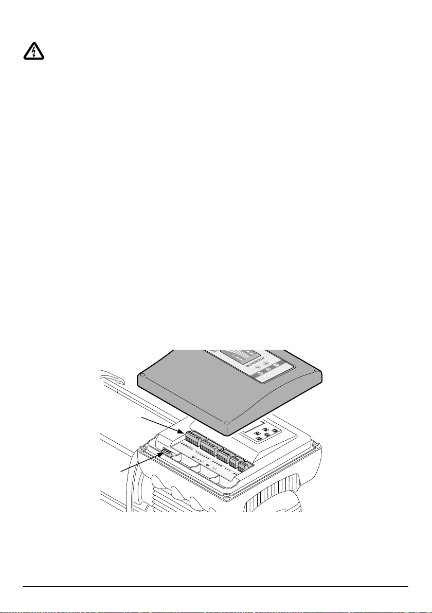
To access the terminals of the connections board, remove the cover of the inverter.
Inside the inverter there is a POWER terminal board (1) and the INPUTS/OUTPUTS terminal board (2)
See the description below of each terminal.
485_1_A
485_1_B
GND
GND
+5V
+24V
+24V
AN1
AN2
GND
GND
COM_1
NO_1
NC_1
COM_2
NO_2
NC_2
GND
IN3
GND
IN1
IN2
485_2_A
485_2_B
4-20
mA
4-20
mA
STOP
2
1
Este manual sirve para los siguientes modelos
2
Tabla de contenidos
Otros manuales de Bomba de agua de PEDROLLO
Manuales populares de Bomba de agua de otras marcas

Sykes AmeriPumps
Sykes AmeriPumps GP100M Guía de solución de problemas

DUROMAX
DUROMAX XP WX Series Manual de usuario

BRINKMANN PUMPS
BRINKMANN PUMPS SBF550 Manual de usuario

Franklin Electric
Franklin Electric IPS Manual de usuario

Xylem
Xylem e-1532 Series Manual de usuario

Milton Roy
Milton Roy PRIMEROYAL Manual de usuario