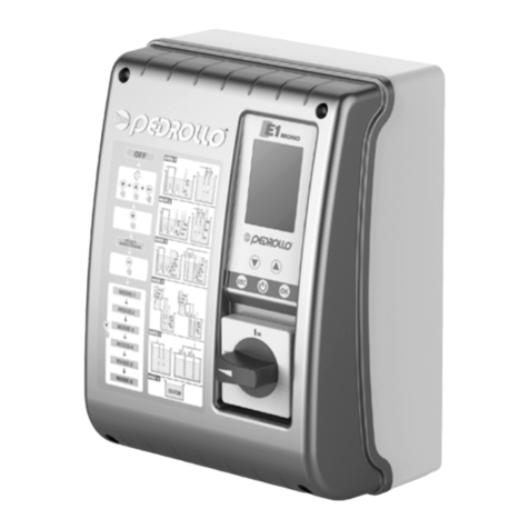
PEDROLLO EVOLUTION Series Manual de usuario

PEDROLLO S.p.A.
Via E. Fermi, 7 – 37047 San Bonifacio - (Verona) - Italy
Tel. +39 045 6136311 – Fax +39 045 7614663
e-mail: sales@pedrollo.com – www.pedrollo.com
MADE IN ITALY
EVOLUTION
QUADRO ELETTRICO PER UN MOTORE CON CONTROLLO DEL COSØ
CONTROL PANEL WITH COSØ CONTROL
IT ISTRUZIONI PER L’USO
EN OPERATING INSTRUCTIONS

INDEX
1. SYMBOLS AND WARNINGS Pag. 3
2. GENERAL INFORMATION Pag. 4
3. WARNINGS Pag. 5
4. TECHNICAL CHARACTERISTICS Pag. 6
5. INSTALLATION Pag. 6
6. FRONT PANEL Pag. 7
7. FUNCTIONS AND PROGRAMMING Pag. 8
8. ALARMS Pag. 11
9. EVOLUTION SINGLEPHASE WIRING DIAGRAMS Pag. 12
10. EVOLUTION THREEPHASE WIRING DIAGRAMS Pag. 13
11. GENERAL CONDITIONS Pag. 14
CONFORMITY DECLARATION Pag. 15
EN – OPERATING INSTRUCTIONS

16
1. SYMBOLS AND WARNINGS
The symbols below indicate hazardous situations that may arise if the prescriptions pro-
vided in this use and maintenance manual are not followed.
DANGER
This warning sign is used when there is a possibility of death and to indica-
te an hazardous situation which may result in severe injuries or damage of
goods. Follow the prescriptions carefully when you see this danger sign.
CAUTION
This warning sign is used when there is a possibility of death and to indica-
te an hazardous situation which may result in severe injuries or damage of
goods. Caution is required.
WARNING
The instructions provided with this sign must be followed to avoid malfun-
ction and damage to the equipment and prevent injury to personnel.
Cut o the power supply before working on the electrical panel or on the system.
The electrical panel must be connected by a qualied electrician according to the
electrical regulations in force.
Connect to an ecient earthing system before executing any other work.
After the system is connected check the settings of the electrical panel since the
electrical pump may start automatically.

2. GENERAL INFORMATION
The panel must always have its manual included in the supply and the manual must be kept
in a handy place available for qualied technicians in charge of use and maintenance of the
system.
We recommend installers/users to read the prescriptions and information in this manual be-
fore using the product, in order to prevent damage or wrong use of the equipment that also
voids the warranty.
Please read carefully this manual and follow the instructions included before starting the equi-
pment.
The indications and instructions included in this manual refer to a standard use of the product;
for special situations, operations or applications that are not listed below please contact our
after-sales service.
Should you need to get in touch with our technical service or to order spare parts please speci-
fy the identication code of the model and the manufacturing number indicated on the plate.
Our after-sales department and service is always available.
The electrical machine supplied must be installed indoors in a ventilated room, with tempera-
ture ranging between +40°C and -5°C.
N.B.: the information included in this manual can be modied without notice. Any damage caused
by these instructions will not be kept in consideration since these instructions are only indicative.
We wish to remind you that non-compliance with indications that we include may cause damage
to persons and goods.
It is however understood that local provisions and/or laws in force must be respected.

18
3. WARNINGS
When goods are received please check that the machine was not damaged during transpor-
tation.
Please notify immediately or however within 5 days from delivery our retailer or PEDROLLO
customer service - if purchased directly from the company - any defect or missing goods.
EVOLUTION electrical panel must be used only for its intended use. Any other application or
use is improper and dangerous.
DANGER
Only specialized technicians acquainted with safety regulations in force can
install and execute maintenance works on EVOLUTION control panel.
It is forbidden to disassemble parts of the panel without PEDROLLO’s ocial authorization:
any unauthorized modication voids all terms of warranty.
Unplug power supply before carrying out any maintenance works or cleaning.
EVOLUTION electrical panel is to be cleaned and stored in a safe place, away from weather
hazards and from accidental risk of falling if it is to be kept out of service for a long period.
DANGER
Do not use water, in case of re near or in the installation area, use suitable
re extinguishing means (power, foam or carbon dioxide).
WARNING
Install the machine in a dry and covered area far from heat sources in com-
pliance with the protection level (IP) declared.
We recommend to install a suitable safety device to protect the power sup-
ply mains of the panel in compliance with the electrical regulations in force.
PEDROLLO cannot be held liable if:
• Installation is not executed properly;
• Not trained personnel uses the panel improperly;
• Maintenance required is not executed properly;
• Non genuine spare parts are used or if spare parts are not suitable for the model;
• Non authorized modications or works are executed;
• Instructions are totally or partially not followed;
• Exceptional occurrences, etc.

4. TECHNICAL CHARACTERISTICS
• Power supply 1~50/60 Hz 230V ±10% (DRYTEK-Mono);
• Power supply 3~50/60 Hz 400V ±10% (DRYTEK-Tri);
• Normally open contact for start;
• Additional normally open contact for enabling of start;
• Pushbuttons for selecting operation and set up;
• Green led indicating motor running;
• Displaying of: volt, ampere, motor COS Ø and alarms;
• Motor’s control on 2 phases;
• Protection from:
- Motor overcurrent (adjustable)
- Phase failure/loss
- Min/max voltage
- Min/max current
• Adjustable COS Ø for dry running protection;
• Auto-restore from protection with 4 independently settable times from 0÷250 minutes;
• Auxiliaries and motor protection fuses;
• Alarm output (com-no-nc resistive load);
• Main switch interlocking door;
• Running capacitor can be added (optional);
• Enclosure in ABS, IP55;
• Ambient temperature: -5/+40 °C;
• Relative humidity 50% at 40 °C (not condensed).
5. INSTALLATION
Check that mains supply is the same as the one indicated on the plate of the electrical panel
and of the motor connected to the panel, then connect “earth” before making any other con-
nection.
EVOLUTION Mono ➞1~ 230V ± 10% 50/60Hz
EVOLUTION Tri ➞ 3~ 400V ± 10% 50/60Hz
Mains supply must be protected with an earthleakage breaker.
Fix the electrical wires in the terminals using a tool of suitable size to prevent xing screw
damage. Special attention is required if using an electric screwdriver.
EVOLUTION is suitable to be xed to the wall with screws and inserts inserted in the holes on
the corners of the box or the brackets, if included.

20
6. FRONT PANEL
electric pump
EVOLUTION 1 v 1.0
Multifunction visualization and programming display;
Green led for load activated;
Multifunction pushbutton;
Arrow up pushbutton;
Arrow down pushbutton;
Ok pushbutton.

7. FUNCTIONS AND PROGRAMMING
MAIN VISUALIZATIONS:
When EVOLUTION turns on the display visualizes the following sequence:
electric pump
EVOLUTION v 1.0
➞ PEDROLLO
www.pedrollo.com
➞ Model 50Hz
es. m/2.2
After the sequence above the display appears as follows:
230v 0.0A 1.0@
Man ( ) Aut (*)
This screen allows to visualize the electrical measures detected by EVOLUTION in each mo-
ment:
• 230V= power supply voltage detected;
• 0.0A= corrent absorbed by the load connected;
• 1.0ϕ= power factor (cos-) of the load connected;
• Man (*)= EVOLUTION on manual mode;
• Aut (*)= EVOLUTION on automatic mode.
LOAD ACTIVATION ON MANUAL MODE:
Push the button and the display shows
230v 0.0A 1.0@
Man (*) Aut ( )
to activate the load,
push the button and check the load is disabled when the led lights up after
releasing the button .
On manual mode the load is activated and it by-passes all the alarms, but in case of a failure
the display ashes and the description of the alarm appears when pushing the button.

22
ACTIVATION OF THE LOAD ON AUTOMATIC MODE:
USER PROGRAMMING:
Push the button and keep it depressed until the display shows
MINIMUM COS-FI
0.70@
with the buttons and set the cos- value so that below this parameter the load
will be disabled for dry running;
i.e. Enable the motor output on manual mode, make the load turn with no load (dry run-
ning) read the cos- data detected (i.e. 0.65) And enter the value with an additional 0.05 on
the screen previously displayed
MINIMUM COS-FI
0.70@
Push the button and on the display the
MAXIMUM CURRENT
5.0A
, appears, with the
and buttons set the value of the current so that if this parameter is exceeded
the load will be disabled for overcurrent;
i.e. Enable motor output on manual mode, read the data of the current with load detected
(i.e. 5.0A) (see that it matches with the data on the motor plate) and enter the value with an
additional 10-15%, on the screen previously displayed
MAXIMUM CURRENT
5.7A
Push the button and
RESET N. 1
TIME 5 MIN , is displayed with the and
buttons set the reset time that allows the system to restart automatically after being
stopped for the rst time by the dry running motor alarm;
Push the button and
RESET N. 2
TIME 10 MIN
, is displayed with the and
buttons set the reset time that allows the system to restart automatically after being
stopped for the second consecutive time by the dry running motor alarm;
Push the button and
RESET N. 3
TIME 15 MIN
, is displayed with the and
buttons set the reset time that allows the system to restart automatically after being
stopped for the third consecutive time by the dry running motor alarm;

Push the button and
RESET N. 4
TIME 20 MIN
, is displayed with the and
buttons set the reset time that allows the system to restart automatically after being
stopped for the fourth consecutive time by the dry running motor alarm;
Push the button and
CYCLICAL RESET
(0) NO (1) YES ?: 1
, pushbuttons set on (0) to stop auto-
matic restart after that the system was stopped for the fourth concecutive time by the dry
running alarm or set on (1) for endless cyclical restart;
the drytek dry running protection system enables restart according to the pro-
gramming time set an resets the restarting cycels each time that the system
detects the presence of water for more than 10sec.
Push the button and wait until the display shows (after the screen sequence described
on page 8:
230v 0.0A 1.0@
Man ( ) Aut (*)
the EVOLUTION panel is ready for use.
Load enabling and disabling (without alarms) of the load is performed by clo-
sing or opening the contact/input normally open G/P (input).
Load enabling is indicated not only by the visualizations on the display but
also by the green light that lights up
Este manual sirve para los siguientes modelos
2
Tabla de contenidos
Otros manuales de Panel de control de PEDROLLO