Oxy Heli oxy2 Manual de usuario
190mm Main Blade
Instruction Manual

435mm
108mm
138mm
415mm
102mm
70
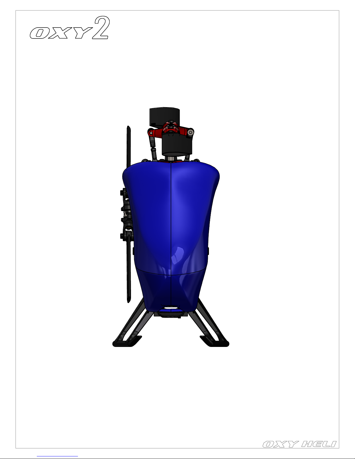
-Standard main rotor diameter
-Standard main blade length
-Main Grip Clamping
-Standard tail rotor diameter
-Standard tail blade length
-Tail Blade Clamping
-Weight
-Maximum motor size
-Maximum battery size
-Recommend battery
: 435mm (with 190mm blades).
: 190mm
: M2 / 3.2 mm root.
: 102-108mm.
: 38 - 41mm.
: M1.6 / 3 mm root.
: 274g (ready to fly excluding batteries)
: diameter 26mm.
: l
ength 72mm, height 25mm, width 35mm, weight 114gr
: 850 45C -1000 mAh 3s 40C max size.....
SPECIFICATIONS
- Visit the Oxy Heli web site www.oxyheli.com to download the latest version of the manual.
- Inside Box 2 you will find your serial number card. Please take a moment to visit the Oxy Heli web site and follow the
instructions to register your helicopter and serial number.
- It is important you take few minutes to register your helicopter and serial number with us. This is the only way to be in contact
with us to receive news, promotional information and technical tips.
- We will also choose five serial numbers each year that will win a discount coupon worth 200USD each to spend at the Oxy Heli
or Lynx Heli web sites.
- Thank you for your purchase, and we wish you the best enjoyment with your new Oxy 2 Helicopter.
VERY IMPORTANT NOTE:
INDEX
Chapter 1 - Specifications
Chapter 2 - Important Notes
Chapter 3 - Required Tools for Assembly
Chapter 4 - What's Inside The Box
Chapter 5 - Pinion Selection & RPM
Chapter 6 - Tail Assembly
Chapter 7 - Main Frame Assembly
Chapter 8 - Align and Lock Frame Panel
Chapter 9 - Transmission Assembly
Chapter 10 - Belt Tension & Adjustment
Chapter 11 - Main Rotor Assembly
Chapter 12 - ESC Installation
Chapter 13 - Flybarless Installation
Chapter 14 - Servo & Servo Rod Prepareration
Chapter 15 - Cylic Servo Installation
Chapter 16 - Tail Servo Installation
Chapter 17 - Landing Gear & Battery Installation
Chapter 18 - Main & Tail Blades Installation
Chapter 19 - Adjustment Servo with Leveler
Chapter 20 - Exploded View
page 2
Chapter 1, Specifications
page 2
page 3
page 4
page 5 - 6
page 7
page 8 - 13
page 14 - 18
page 19
page 20-21
page 22
page 23-25
page 26
page 27
page 28
page 29
page 30
page 31
page 31
page 32-33
page 34-37

NOTES FOR ASSEMBLY:
Please read this instruction manual fully before beginning assembly of this model helicopter. Be sure to use quality tools during
the assembly process, and remember not to overtighten small fasteners. Note the following symbols which are used in this manual.
Use thread lock sparingly where indicated. If you are unsure about an assembly step, please seek the advice of an experienced
pilot. Warranty on any parts is only applicable prior to assembly of the part on the model.
NONE OF THE PRE ASSEMBLED PARTS HAVE THREAD LOCK ON THE SCREWS. IS IMPORTANT TO READ AND FOLLOW THE ASSEMBLY
NOTES IN EACH STEP. INCORRECT ASSEMBLY OR NOT USING THREAD LOCK WILL CAUSE A CRASH OR INJURY.
IMPORTANT NOTE:
This model helicopter has been designed and produced to be a high performance 3D machine. With its simple design and low
parts count, pilots of all skill levels will appreciate its easy repairability. This is not a toy. Please take care assembling the model,
and take care and responsibility when you fly it. We take no responsibility for any damage or injuries, either direct or consequential,
from the use of this product. If you are not experienced in the assembly and flying of a high performance model helicopter we
recommend you seek the assistance of an experienced pilot. Above all, fly safely and we hope you enjoy this model.
SAFETY GUIDELINES:
Only fly this model in areas designated for the use of model aircraft. Ensure you obtain indemnity insurance, normally available
through your National model aircraft association. Remain at least 6 meters (20 feet) from the model at all times. Never allow
spectators or animals any closer than 30 meters (100 feet) from the model.
Use Loctite 648 Bonding
Important note
Use Loctite 243 Medium Strength
Use CA Glue
Use Silicone Grease
Chapter 2, Important Notes
page 3

TOOLS REQUIRED
Small Tip - Flat Screw Driver
1.5mm Hex Screw Driver
(High quality)
Two Tools Required
1.3mm Hex Screw Driver
(High quality)
Caliper
Needle nose pliers
Uniball Pliers
Chapter 3, Required Tools for assembly
page 4
Philips head screw driver

Chapter 4: What's inside the box
INSIDE THE MAIN BOX
Box 3/Bag 1 Tail Boom Set,
Box 3/Bag 2 190mm CP Main Blade
Serial Number Card,
Box 2/Bag 1 Boom Clamp Set,
Box 2/Bag 2 Battery Tray Set,
Box 2/Bag 3 Main Gear Set,
Box 2/Bag 4 Accessories,
Box 2/ Bag 5 Extra Hardware,
Canopy,
BOX 1-1,
Box 1/Bag 11 Main Frame Set,
Box 1/Bag 10 Landing Gear Set,
Tail Set Asembly Parts.
MAIN BOX
page 5

Chapter 4: What's inside the box
INSIDE THE BOX 1
BOX 1
Box 1/Bag 10
Landing Gear Set
Tail Set Asembly Parts
Canopy
Head Set Assembly Parts
Frame Set Assembly Parts
Box 1/Bag 11
Main Frame Set
page 6

OXY 2 POWER SYSTEM AND HEAD SPEED SET-UP
In order to choose the best setup for your Oxy 2, and optimize performance, it is important to know some basic information:
1- Motor Kv – Min 3600 - Max 6000 - See your motor specification
2- Battery Pack – (3s or 4s)
3- Your target head speed
If you use a head speed calculator, use
110T for the main gear and one of the available pinions 10T – 11T – 12T – 13T – 14T – 16T – 18T .
The kit comes with one pinions (12T-2mm Shaft ) which enables a wide head speed range with 3s batteries and 5500Kv Motor perfect for novice
and expert pilots.
Head Speed Note:
Although Oxy 2 can handle very high Head Speed, we suggest not to exceed 5500 RPM to maintain a good
compromise btw performances and efficiency.
Configuration examples
Since the Oxy2 is a high performance 3D RC helicopter, we suggest using high quality power components including motor, battery and
ESC. Remember the Oxy 2 is a 200 class heli – use light components to maximize flight time and performance.
Here are some suggestions:
-
Motor: Suggested KV 3600KV to 6000KV, 16-11 to 19-12 caliber series (stator diameter – stator length).
-
Battery: 3 or 4S with capacity from 800 to 1000mAh / 45C discharge rate. Maximum size: length 72mm, height 25mm, width
35mm, weight 114g.
-
ESC: 25 to 30A – with BEC 5V or higher.
-
Cyclic servos: Standard Sub MICRO size servo speed: =>0.06 sec/60 at 6V.
-
Rudder servo: Standard MICRO size servo – speed =>0.06 sec/60 at 6V – a specific rudder servo is suggested for best tail
authority.
-
FBL system: The Oxy 2 was designed around the U-Ikon / U-Brain and Neo V-Bar Systems. But many other smaller size FBL systems
can be used, depending on your personal choice. Max inner Frame dimension 26mm.
-
Main blade: The Oxy 2 can fly with plastic or CF main blades from 190 to 210mm. Our testing was with Lynx 190mm Carbon Plastic main
blades, and Zeal 210mm main blades. The Oxy 2 main grips use M2 clamp screw and have a 3.2 mm root.
-
Tail blades: The Oxy 2 uses our own OEM tail blades, either 38 or 41mm (included with the kit). They use a M1.6 clamp screw and
3 root.
We offer 38 and 41mm tail blades to suit different head speeds. Use 41mm tail blades when your head speed is lower than
4500rpm and 38mm with higher head speeds.
page 7
Chapter 5: Pinion Selection & RPM
Oxy 2 Gear Ratio Chart
Oxy 2 Fly Style / Head Speed / Main Blade / Tail Blade / Max Pitch suggestion chart:

Chapter 6: Tail Assembly
OXY0516 - Tensioner Spacer
OXY0279-Vertical Fin
Bearing Bushing
2 x SMR682Z-ZZ-
2.5X6X2.6 Radial Bearing
OXY0524-
2.55x4.5x0.1 Shim
OXY0515-
Tensioner Bushing
2 x MR52-W2
2X5X2 Radial Bearing
2 x SMR682Z-ZZ-
2.5X6X2.6 Radial Bearing
OXY0524-2.55x4.5x0.1 Shim
OXY0543-Al Tail Case
OXY0527-
2x3.5x0.1 Shim
Tail Case Assembly
(Box 1/Bag 2)
2 x SMR682-ZZ-
2X5X2.3 Radial Bearing
OXY0524-
2.55x4.5x0.1 Shim
OXY0253-Tail Hub
2 x OXY0551-1.5x2.8 H0.4 Washer
2 x M1.4x3 Pan Head Screw
OXY0521-Linkage Ball
Vertical Fin Assembly
(Box 1/Bag 1)
Important Note:
This part comes pre assembled
WITHOUT thread lock. It MUST be
re-assembled with thread lock as shown.
Tail Rotor Assembly
(Box 1/Bag 3)
OXY0257-Vertical Fin
Important Note:
This part, for tuning reasons,
comes factory pre assembled,
it ready to use
Important Note:
This part, for tuning reasons,
comes factory pre assembled,
it ready to use
Important Note:
This part, for tuning reasons,
comes factory pre assembled,
it ready to use
Important Note:
This part, for tuning reasons,
comes factory pre assembled,
it ready to use
page 8

Tail Shaft Assembly
(Box 1/Bag 4)
Tail Pitch Slider Assembly
(Box 1/Bag 5)
Tail Belt Crank Assembly
(Box 1/Bag 6)
Important Note:
This part, for tuning reasons,
comes factory pre assembled,
it ready to use.
Important Note:
This part, for tuning reasons,
comes factory pre assembled,
it ready to use.
Important Note:
This part, for tuning reasons,
comes factory pre assembled,
it ready to use.
Important Note:
This part comes pre assembled,
WITHOUT THREAD lock. Follow
the instruction for final assembly.
Do not over tighten
Pan Head Screw 2XM1.4x4
2 x MR52-W2-
2X5X2 Radial Bearing
2 x OXY0460 -
Bell Crank Bushing
2 x OXY0448 - Bell Crank
Pin Screw
OXY0252 - Al Tail
Bell Carnk
Tail Shaft 16T
OXY0457 - Tail Pitch
Slider Bushing
OXY0255 - Tail pitch
Slider Haft Moon
2 x MR683-3x7x2
Radial Bearing
OXY0541 - Tail Pitch
Slider Ring
2 x M1.4x4
Pan Head Screw
2 x OXY0523-Link
Control Bushing
2 x OXY0522-
Link Control
Chapter 6:Tail Assembly
page 9

REF 1mm
REF >= 1.3mm
Important Note:
This part, for tuning reasons,
comes factory pre assembly,
it ready to use.
Important Note:
This part, for tuning reasons,
comes factory pre assembly,
it ready to use.
Note: to install this
pin screw rotate
counter clock wire.
Note Pin Screw Thread:
Oxy designed the Pin Screw with
a counter clockwise thread. This
will help on the final locking
operation. Be careful to follow our
instructions to get a perfect assembly.
Step 1: Step 2:
Step 3: Step 4:
Step 5:
OXY0067
Guide Push Rod
2 x OXY0539-
Pin Screw
OXY0578 - Tail Boom STD
Push the part inside the
boom sockets as shown.
Slide the parts as shown
In order to lock the tail push rod
support, use a Flat Screw Driver
and turn clockwise. Do not
over tighten.
OXY0584-STD Tail Push Rod
OXY0536-Al Tail Push
Rod Terminal
OXY0519-Threaded
Rod M1.4X7mm
OXY0526-Plastic
Linkage Ball 3mm
Carbon Fiber Tail Push Rod Assembly
(Box 3/Bag 1)
Tail Push Rod Guide Assembly
(Box 3/Bag 1)
Note: Install the Pin Screw
and leavea gap as shown.
Chapter 6: Tail Assembly
page 10
Este manual sirve para los siguientes modelos
1
Tabla de contenidos
Otros manuales de Juguete de Oxy Heli

Oxy Heli
Oxy Heli 5 Manual de usuario

Oxy Heli
Oxy Heli Tareq OXY3 Manual de usuario

Oxy Heli
Oxy Heli OXY4 360NB Manual de usuario

Oxy Heli
Oxy Heli OXY4-MAX Edition 380 Manual de usuario

Oxy Heli
Oxy Heli OXY3 SPEED Manual de usuario

Oxy Heli
Oxy Heli OXY3 SPEED Manual de usuario

Oxy Heli
Oxy Heli OXY4 Manual de usuario

Oxy Heli
Oxy Heli OXY3-SNB Manual de usuario

Oxy Heli
Oxy Heli OXY3 SPEED Manual de usuario

Oxy Heli
Oxy Heli OXY2 Sh Manual de usuario


