OpenScan Classic Manual de usuario

1
OpenScan –User Manual

2
Contents
Material needed...................................................................................................................................... 3
3D printable parts.................................................................................................................................... 5
Assembly ................................................................................................................................................. 7
Step 1 –LCD......................................................................................................................................... 7
Step 2 –Control unit............................................................................................................................ 8
Step 3 –wiring the LCD ....................................................................................................................... 9
Step 4a –Stand 1............................................................................................................................... 10
Step 4b –Stand 1............................................................................................................................... 11
Step 5 –Stand 2................................................................................................................................. 12
Step 6 –Turntable ............................................................................................................................. 13
Step 7 –Tilting mechanism ............................................................................................................... 14
Step 8 –Setting the Scanning Volume .............................................................................................. 15
Step 9 –Wiring the stepper motors and control unit....................................................................... 16
Step 10 –(optional) Mounting on a base plate / work surface ........................................................ 17
Accessories............................................................................................................................................ 18
Remote Control –Bluetooth for Android/iOS................................................................................... 18
Remote Shutter Control –Infrared ................................................................................................... 19
Remote Shutter Control –Modifying a remote control.................................................................... 20
Using the control unit (important notes!)............................................................................................. 21
Main Menu........................................................................................................................................ 21
Load/Start Program........................................................................................................................... 21
Run last program........................................................................................................................... 21
Load Program ................................................................................................................................ 22
Home –Rotor and Home –Turntable........................................................................................... 22
Programmablauf............................................................................................................................ 22
Interrupt or Stop Routine.............................................................................................................. 23
Settings.............................................................................................................................................. 23
Modify Program............................................................................................................................. 23
Time per photo.............................................................................................................................. 24
Min. vertical angle......................................................................................................................... 24
Set Camera mode / Triggering mechanism................................................................................... 25

3
Material needed
M3 nut
8
M3x12mm
10
M3x8mm
8
Steel pin (d=6mm, l>50mm)
2
Jumper Wire 10cm m-f
4
Nema 17 (min. 40Ncm)
2
Stepper motor cable >70cm
JST-XH-4P or 4P DuPont
2
LCD 20x4 with I2C-Module
1

4
Power Supply 12V 2A
Barrel connector (5,5mm-
2,5mm)
1
Control unit
1
Remote Control Bluetooth
(optional)
1
Remote Control Infrared
(optional)
1


6
Control_Module.stl
1
Gear_Small.stl
(optional v2 je nach
Druckertoleranz)
1
Turntable_Adapter.stl
(Optional: je nach
Bedarf)
1
Accessories for assembly:
Allen Key (2,5mm)
1
Optional: pliers
1

7
Assembly
Step 1 –LCD
Needed parts:
LCD 20x4 with I2C-Modul
Control_module.stl
M3x12 (4x)
M3 nuts (4x)
Front:
Back:
Description:
The display is mounted on the back of the control unit using four of the M3x12mm screws. See the
orientation of the display - I2C module top right.
Note:
Depending on the printing accuracy, it may be necessary to pre-drill the screw holes with a 3mm drill
bit.
I2C-Module

8
Step 2 –Control unit
Needed parts:
Control unit
Control_module.stl (nach Schritt 1)
M3x12 (4x)
M3 nuts (4x)
Front:
Back:
Description:
The control unit is mounted on the back of the printed unit using four of the M3x12mm screws.
Note:
Depending on the printing accuracy, it may be necessary to pre-drill the screw holes with a 3mm drill
bit. It may also be necessary to deburr / enlarge the holes for the push buttons on the front.

9
Step 3 –wiring the LCD
Needed parts:
Control unit (after Step 2
Jumper Wire 10cm m-f
Back:
Description:
Wire the connections according to their labels. (GND-GND / VCC-VCC / SDA-SDA / SCL-SCL)
Important note:
This step should be double checked to ensure that the pins are properly connected, otherwise the
control unit and / or the display can be destroyed!
10
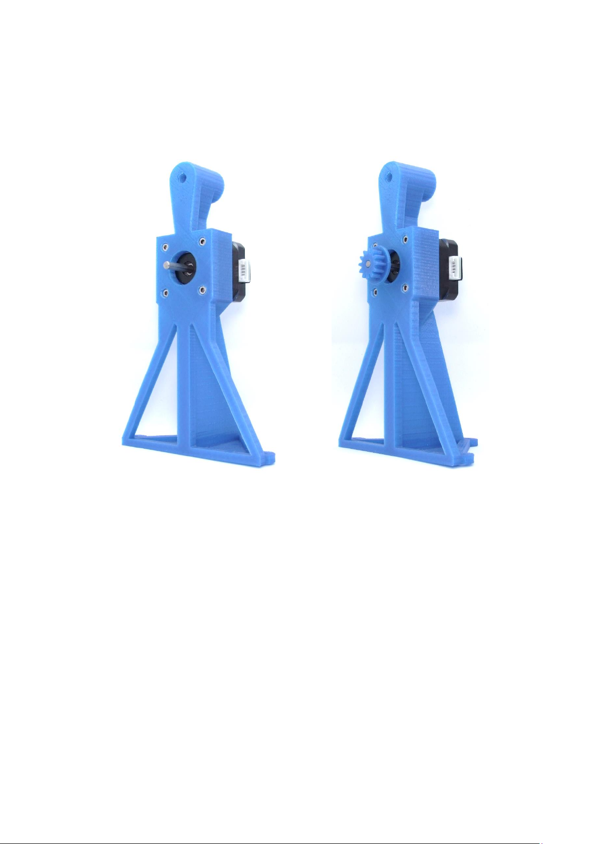
Step 4a –Stand 1
Needed parts:
Stand1_Nema_17.stl
Nema 17 (min. 40Ncm)
M3x8mm (4x)
Gear_Small.stl (optional v2)
(1) (2)
Description:
(1) Mount the stepper motor with four M3x8mm Screws onto the Stand1.stl.
(2) Press the Gear_small.stl onto the motor shaft. Make sure, that the gear and the motor shaft close
flush at the front.
Note:
Depending on the printing accuracy, it may be necessary to pre-drill the screw holes with a 3mm drill
bit. Furthermore the gear and the motor shaft might have a tight fit and you might have to „gently“
use the help of a hammer.
Tabla de contenidos
Otros manuales de Escáner de OpenScan


