Noyes OFL 100 Mini-OTDR Manual de usuario

Operations Manual
for the
OFL 100 Mini-OTDR
Rev.F
January 13, 1999
PartNumber:OFL1-00-1000
Noyes OFL-100 LR Specs
Provided by www.AAATesters.com

i
Contents Page
1.0 General Information...........................................................................................................1
1.1 Unpacking and Inspection ...................................................................................................................... 1
1.2 Precautions .............................................................................................................................................. 1
1.3 Recommended Accessories .................................................................................................................. 2
2.0 Functional Description ......................................................................................................3
2.1 Panel Buttons & Connector Ports .......................................................................................................... 4
3.0 OFL 100 Operation.............................................................................................................6
3.1 Power-Up Sequence................................................................................................................................. 6
3.1.1 HR and MM Models ........................................................................................................................ 6
3.1.2 LR Models ....................................................................................................................................... 6
3.1.3 DM and DS Models ......................................................................................................................... 7
3.2 Selecting Operational Parameters ......................................................................................................... 8
3.2.1 HR, LR and MM Models.................................................................................................................. 8
3.2.2 DM and DS Models ....................................................................................................................... 11

ii
Contents Page
3.3 VerifyingTest Conditions ...................................................................................................................... 14
3.3.1 HR, LR and MM Models................................................................................................................ 14
3.3.2 DM and DS Models ....................................................................................................................... 15
3.4 Locating the End of the Fiber ............................................................................................................... 16
3.4.1 HR, LR and MM Models................................................................................................................ 16
3.4.2 DM and DS Models ....................................................................................................................... 17
3.5 Plotting a Trace ...................................................................................................................................... 18
3.5.1 HR, MM, DM and DS Models ........................................................................................................ 18
3.5.2 LR Models ..................................................................................................................................... 19
3.6 Saving aTrace in the OFL 100 .............................................................................................................. 21
3.6.1 MM and HR Models ...................................................................................................................... 21
3.6.2 LR Models ..................................................................................................................................... 22
3.6.3 DM and DS Models ....................................................................................................................... 22
3.7 Saving aTrace to a PC........................................................................................................................... 24
3.7.1 HR and MM Models ...................................................................................................................... 24
3.7.2 LR Models ..................................................................................................................................... 24
3.7.3 DM and DS Models ....................................................................................................................... 24
3.8 Scanning for Events .............................................................................................................................. 26
3.8.1 HR, MM, DM and DS Models ........................................................................................................ 26
3.8.2 LR Models ..................................................................................................................................... 27

iii
Contents Page
4.0 Maintenance andTrouble Shooting ................................................................................29
4.1 Repair And Calibration.......................................................................................................................... 29
4.2 Battery Maintenance.............................................................................................................................. 29
4.3 Optical Connector Maintenance ........................................................................................................... 30
4.4 Getting Technical Support .................................................................................................................... 30
5.0 Warranty Information.......................................................................................................31
5.1 Exclusions .............................................................................................................................................. 31
5.2 Warranty Registration ........................................................................................................................... 31
5.3 Returning Equipment ............................................................................................................................ 31
Appendix A: OFL 100 Specifications...................................................................................32
Appendix B: RS-232 Pin Designations for PC Cable..........................................................33

iv

1
1.0 General Information
Thank you for purchasing the Noyes Fiber Systems OFL 100
OTDR. The OFL 100 is designed to be a rugged, reliable,
portable test instrument having the many features required to
measure and maintain fiber optic networks. Its’ easy “one
button” operation provides event location, length
measurements, splice loss measurements, and trace
documentation. This instrument utilizes standard OTDR
(Optical Time Domain Reflectometer) technology to make
measurements. When used with an optional thermal printer or
with the supplied PCPLOT3 software it will provide complete
fiber network documentation and trace analysis.
1.1 Unpacking and Inspection
This instrument has been carefully packed in accordance with
standard shipping procedures. Should damage be observed
as a result of shipment, or if any of the following items are not
included, please notify Noyes Fiber Systems at 603-528-7780
or 800-321-5298.
• OFL 100 OTDR
• Carrying Case
• User Guides
• AC Power Adapter
• Serial Cable
• Warranty Registration Card
• Trace Recording Note pads
• PCPLOT3 Trace Analysis Software diskettes
1.2 Precautions
Use care when working with any optical transmission
equipment. It is good practice to avoid looking directly at the
outputofanyopticalfibersorsources. Referto yourcompany’s
safety procedures when working with optical systems.
2
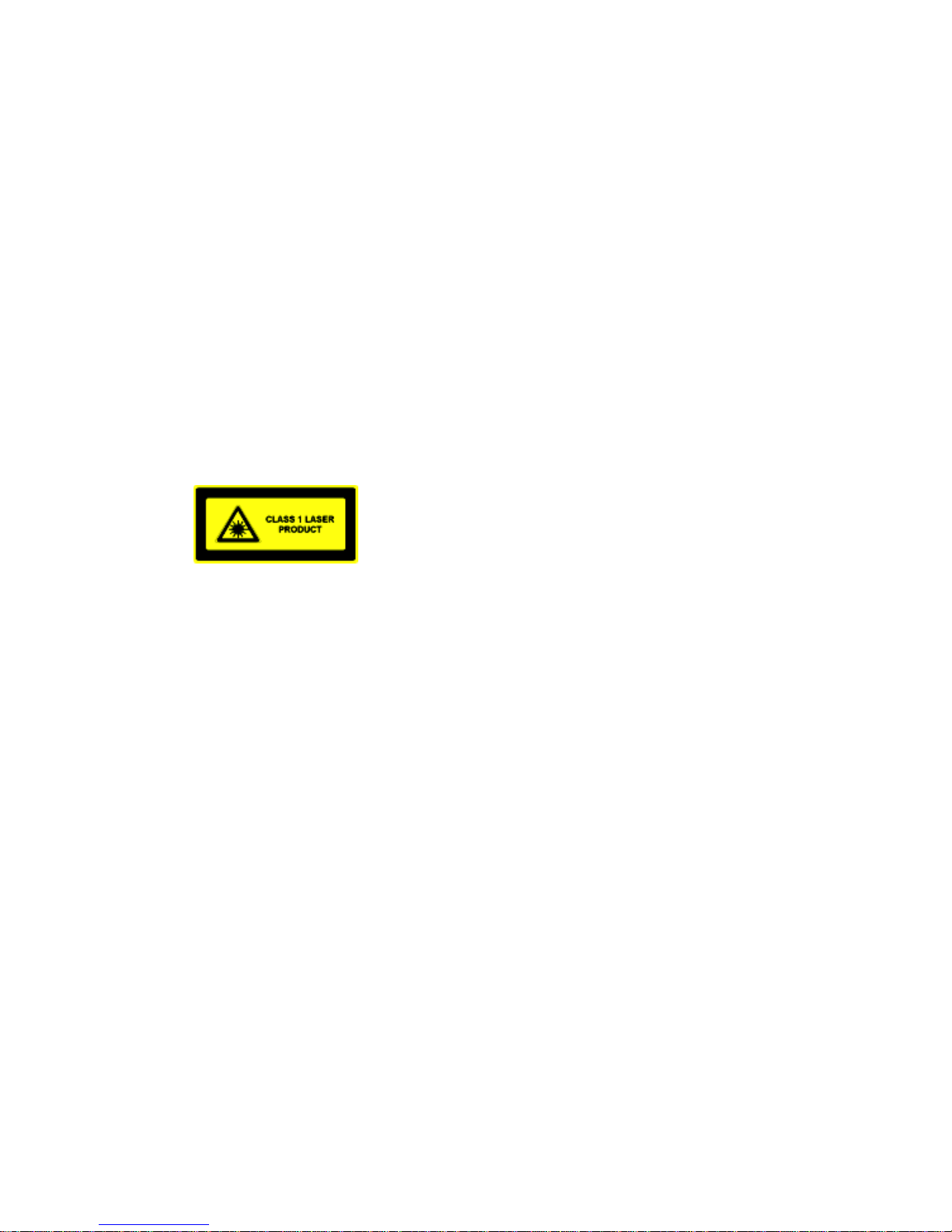
CAUTION: Use of controls or adjustments other than those
specified herein may result in hazardous radiation exposure.
The OFL 100 is a CLASS 1 LASER PRODUCT.
It is important to keep all optical connections and surfaces free
fromdirt,oils,orothercontaminantstoensureproperoperation.
Proper cleaning techniques must be performed on fiber
connectors, connector adapters, etc., before conducting any
test procedures that are outlined in this manual. Please refer
tothesection on maintenance formoreinformationoncleaning
methods. Scratched or contaminated connectors can reduce
systemperformance. Alwaysreplaceprotectivedust capswhen
available.
1.3 Recommended Accessories
Jumper cables are required to interface the OFL 100 to the
fiber under test (be certain the jumper cables used are the
same core/cladding size as the fiber under test). One end of
the jumper cable must interface to the front panel connector on
the OFL 100. The other end can be any number of styles,
allowing connection to different systems. Various cable styles
and lengths are available from Noyes Fiber Systems.
A supply of industry approved optical cleaning pads would be
helpful to maintain optical connectors. Also, a can of filtered
compressed air is useful for blowing contaminates out of
connector adapters.

3
2.0 Functional Description
Using standard optical time domain reflectometer (OTDR)
techniques, the OFL 100 transmits a short pulse of light down
theopticalfiber and examinesthe reflections coming back. The
reflections are known as backscatter. The OFL 100 interprets
these reflections and determines event losses, distances and
the fiber end. Optical time domain reflectometry allows the
user to identify problems on a system while having access to
only one end of the fiber.
• Event Location
The OFL 100 can be used to automatically locate events using
the SCAN command, or manually by using the PCPLOT3
software. Each event location will be displayed along with the
event magnitude measured in dB.
• End Detection
TheOFL 100 can beusedto measure the lengthofaninstalled
cable. Itis also useful to verify cablelengthsprior to installation.
• Fiber Trace Documentation
TheOFL100providesOTDRtracedocumentationviatheserial
port. Directplottingoftracesis possiblebyconnectingathermal
printer. The OFL 100 can be connected toapersonalcomputer
for computer storage of traces. For more information on the
availablePC featuresplease refertothePCPLOT3user’sguide.

4
2.1 Panel Buttons & Connector Ports
Please refer to the front panel drawing to the right when
becoming familiar with the OFL 100.
1. Optical Port - The optical port allows connection to various
fiberoptic jumper cables. Tocleantheoptical connector please
refer to the maintenance section.
2. AC Adapter Input - The OFL 100 is designed to operate
continuously with the AC adapter plugged in. Depending upon
model the OFL 100 will operate for approximately 4-6 hours
from a fully charged battery. A “LOW BATT” message will
appear in the display when the battery voltage is low. The AC
adapter should be inserted at this time.If it is not, the OFL 100
will still operate for up to one hour before shutdown occurs.
Please note that the AC adapter will have a blue band wrapped
around the end of the cord corresponding to the blue dot on
the OFL 100.

5
3. Serial Port- A DB9 connector is providedforthe downloading
oftracestoanexternalprinter or PC.Please refertothe section
3.7 for more information.
4. Soft Arrow Keys - These keys “point” to the words displayed
in the bottom row of the Liquid Crystal Display (LCD). By
pressing these keys you select the function, or parameter
displayed above it. Because the meaning of the soft keys may
change from screen to screen they will be referred to by the
function or parameter displayed above the key. For example:
In the above display, if the manual says “Press SETUP”, you
should press the soft arrow key below the word “SETUP”.
5. Power Key - Pressing the ‘POWER’ key will turn the unit on
or off. See section 3.1 for more information on the events that
occur during power up.
6. Menu Key - At anytime during the operation of the OFL 100
you may choose to return back to the main menu by selecting
this key.
Main Menu
7. Display - The OFL 100 incorporates a 2 x 20 Alphanumeric
Liquid Crystal Display (LCD) for listing menu selections and
displaying fiber information.
[MENU] [ ]
SETUP [ac] LOCATE
[MENU] [ ]
SETUP [ac] LOCATE
Tabla de contenidos
Otros manuales de Equipo de prueba de Noyes


Manuales populares de Equipo de prueba de otras marcas

SMART
SMART KANAAD SBT XTREME 3G Series Manual de usuario

Agilent Technologies
Agilent Technologies BERT Serial Manual de usuario

Agilent Technologies
Agilent Technologies N3280A Manual de usuario

Vernier
Vernier Go Direct Voltage Manual de usuario

Lifeloc
Lifeloc R.A.D.A.R. Manual de usuario

Fluke
Fluke T5-600 Instrucciones de funcionamiento e instalación


