Nlynx Gemini Express Manual de usuario

GEMINI EXPRESS MULTIPLEXER
User’s Guide

2
TABLE OF CONTENTS
SAFETY 3
Federal Communications Commission (FCC) Statement 3
Classification of LED Transmitter Device 4
INTRODUCTION 5
UNPACKING 6
ACTIVE PAIR SETUP 7
DESCRIPTION 8
CONFIGURATION 9
MODE DESCRIPTION 10
COLLAPSED RINGS 11
CONNECTIONS 12
INSTALLATION 16
Host side multiplexer installation 16
Device side multiplexer installation. 17
PROBLEM SOLVING 19
The MULTIPLEXER ’s front panel power LED is off! 19
The MULTIPLEXER’s RX LED is off or flashing! 19
The MULTIPLEXER ’s TX LED is off! 19
A device is down or unstable! 19
Devices interfere with each other! 20
Devices cannot operate in Express mode! 20
Flashing Express LEDs! 20
Express LEDs on without data activity! 20
SPECIFICATIONS 21
WARRANTY STATEMENT 23
RETURN MERCHANDISE PROCEDURE 23

3
SAFETY
Note: READ THIS FIRST
1. Do not look into any fiber optic connection or fiber optic cable.
2. Do not connect GEMINI EXPRESS MULTIPLEXER to any type of public
network.
3. Do not connect any outdoor cabling to the GEMINI EXPRESS
MULTIPLEXER without proper lightning protection.
4. Do not use unauthorized power supplies or cables.
5. Do not connect to non-5250 protocol devices.
6. Do not disassemble or modify the power supply and its cables.
7. Disconnect all cables prior to configuration.
8. Devices attached to the UTP network must comply with the voltage and
current limits for Class 2 Power-Limited Signal Circuits as defined by
article 725 of the National Electrical Code and Section 16 of the Canadian
Electrical Code.
9. For your safety, receptacles must be properly wired and grounded.
10. Never attempt to service equipment connected to the data cable network or
the grounded receptacle during an electrical storm. Exposure to lethal
voltages may occur when lightning is present.
The following FCC statement applies to the NLynx GEMINI EXPRESS
MULTIPLEXER.
Federal Communications Commission (FCC) Statement
Note: This equipment has been tested and found to comply with the limits for a
Class A digital device, pursuant to Part 15 of the FCC Rules. These limits are
designed to provide reasonable protection against harmful interference when the
equipment is operated in a commercial environment. This equipment generates,
uses, and can radiate radio frequency energy and, if not installed and used in
accordance with the instruction manual, may cause harmful interference to radio
communications. Operation of this equipment in a residential area is likely to
cause harmful interference, in which the user will be required to correct the
interference at his own expense. Unauthorized changes or modifications could
void the user’s authority to operate the equipment.
This device complies with Part 15 of the FCC Rules. Operation is subject to the
following two conditions: (1) this device may not cause harmful interference,
and (2) this device must accept any interference received, including interference
that may cause undesired operation.

4
Classification of LED Transmitter Device Important:
The optical transmitter contains an LED system and is classified “CLASS 1
LED PRODUCT” per EN60825-1 (+A11), Safety of Laser Products. Contact
NLynx Technologies for repair if your GEMINI EXPRESS MULTIPLEXER
ever requires maintenance.

5
INTRODUCTION
This user's manual presents the GEMINI EXPRESS MULTIPLEXER for use
with the IBM 5250 protocol. The 5250 family of products consists of the IBM's
System 34, 36, 38, and the AS/400 along with many supporting devices
manufactured by IBM and other companies. The GEMINI EXPRESS
MULTIPLEXER works with all supporting devices that are designed within the
5250 specifications.
GEMINI EXPRESS MULTIPLEXER
Decision Data’s MULTIPLEXER Gemini Eight-Port Express Fiber Optic
Multiplexer offers the unique ability to allow multiple AS/400 controller polling
groups to be transmitted over a single fiber optic pair. This feature allows all
new AS/400e controllers to provide their maximum throughput potential, in
either 1Mbps Optimized or 2Mbps Express mode, by transparently multiplexing
the "split-polling" feature without requiring performance robbing PTF's. All
new IBM controllers support the "split-polling" feature as a means of achieving
higher throughput rates, even when connected to standard legacy devices. The
Gemini Express Multiplexer allows the "split-polling" feature to remain
"enabled" with performance of up to 4 times greater than standard legacy 1Mbps
5250 protocol. The Gemini Express Multiplexer has 8 Shielded RJ45 port
connections as well as a DB25 "direct-connection" eliminating the need for the
twinax "brick" and associated twinaxial cabling. Link connectivity is via ST
fiber optic multi-mode connection with ability to operate in both point-to-point
and multi-point "ring" topologies, reducing hardware requirements by up to
50%. Other features include Advanced Noise Filtering, LED Port Diagnostics,
Configurable UTP Pin Assignments, and a Field Replaceable wide-ranging
Power Supply.

6
UNPACKING
Remove the packing material and check for the items below:
GEMINI EXPRESS MULTIPLEXER
A (100-240 VAC) input external power supply is attached on the rear panel.
USER'S MANUAL AC POWER CORD
(North American units only)
Visually inspect all items for damage. If any component is damaged, contact
NLynx Technologies for a replacement.
DO NOT APPLY POWER TO ANY DAMAGED COMPONENT!
Gemini Multiplexe
r
Users Guide
NLyn
x

7
ACTIVE PAIR SETUP
All GEMINI EXPRESS MULTIPLEXERS can be factory configured per
customer request. The factory default setting is Pins 4 & 5. Different
configurations will be indicated on the label on the bottom of the unit.
IDENTIFICATION LABEL
The active pair may be re-configured by performing the following procedure:
• Disconnect all power to the unit.
• Remove the two top cover screws located on the rear panel.
• Gently slide the top cover back one inch.
• Hold the top cover and tilt it up.
Reconfigure the jumpers located behind the RJ45 connectors as required.
Settings for polarity and active pair assignment are shown below:
ACTIVE PAIR JUMPER SETTINGS
It should be noted that connections to the DB25 and the RJ45s are mutually
exclusive. If any of the three pairs of the RJ45 are selected, the DB25 is
disconnected. If the DB25 is selected, the RJ45s are disconnected. All jumper
settings must be identical. To reinstall the top cover, tilt the top cover down, and
slide the top cover forward until it mates completely with the bottom cover.
Install the 2 top cover screws.
RJ45 RJ45 RJ45
RJ45 (4/5) RJ45 (3/6) RJ45 (1/2)
RJ45
DB25

8
DESCRIPTION
The GEMINI EXPRESS MULTIPLEXER’s indicators and connections are
described below.
Power LED Amber LED activates when the GEMINI EXPRESS
MULTIPLEXER is powered up.
TX Activity LED Green LED activates when a signal is transmitted to the fiber
optic aggregate link.
RX Activity LED Green LED activates when a signal is received from the fiber
optic aggregate link and the MULTIPLEXER synchronizes to it.
Polling Group Status LEDs The upper green LEDs are express mode
indicators. These LEDs activate when an express signal is detected and remain
on until a 1MBPS signal is detected or a system reset occurs. The lower green
LEDs are data activity indicators. These LEDs activate when a signal is present.
Polling Group Connectors There are two polling groups. Each polling group
has been divided into two port groups. Polling group #1 consists of ports 0 - 3
(port groups A & B) and Polling group #2 consists of ports 4 - 7 (port groups C
& D). Ports within a polling group must be connected to ports from a common
controller.
PRODUCT
DC POWER
CONNECTION
I
DENTIFICATION
LABEL FCC LABEL
EXTERNAL POWER SUPPLY
REAR VIEW
DB25
CONFIGURATION
SWITCHES
FIBER
OPTIC
LINK
Power
LED Fiber
Status
LEDs
Polling
Group 1
Polling
Group 2

9
CONFIGURATION
The configuration switch settings are shown below.
1 2
ON
HOST SIDE MULTIPLEXER POINT TO POINT MODE
CONFIGURATION SWITCHES
SWITCH 1: ON
SWITCH 2: ON
LEGEND
1 2
ON
HOST SIDE MULTIPLEXER
RING MODE
CONFIGURATION SWITCHES
SWITCH 1: ON
SWITCH 2: OFF
LEGEND
1 2
ON
DEVICE SIDE
MULTIPLEXER
POINT TO POINT MODE
CONFIGURATION SWITCHES
SWITCH 1: OFF
SWITCH 2: ON
LEGEND
1 2
ON
DEVICE SIDE
MULTIPLEXER RING MODE
CONFIGURATION SWITCHES
SWITCH 1: OFF
SWITCH 2: OFF
LEGEND

10
MODE DESCRIPTION
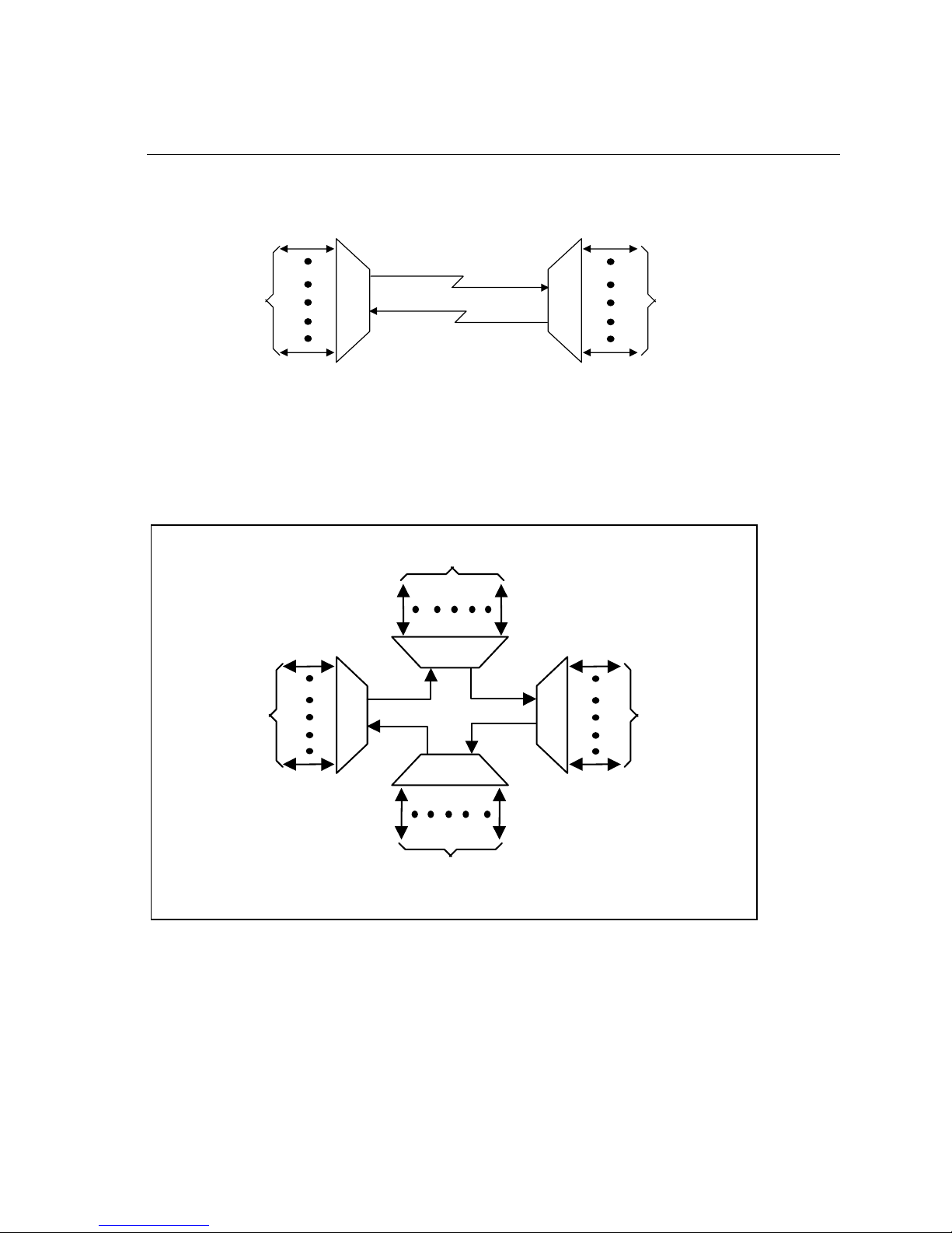
A “POINT TO POINT” link is comprised of two Multiplexer s connected by a
single backbone. A diagram of a “POINT TO POINT” link is provided below.
Multiple Multiplexers which are connected in series with fiber optic transmit to
fiber optic receive constitute a “RING” topology. A diagram of a
“RING”application is provided below.
FIBER OPTIC BACKBONE
MULTIPLEXER
MULTIPLEXER MULTIPLEXER
MULTIPLEXER
HOST PORT
HOST PORT
CONNECTIONS
CONNECTIONS
DEVICE
DEVICE
CONNECTIONS
CONNECTIONS
DEVICE
DEVICE
CONNECTIONS
CONNECTIONS
DEVICE
DEVICE
CONNECTIONS
CONNECTIONS
TX
TX
TX
TX RX
RX
RX
RX
FIBER OPTIC BACKBONE
MULTIPLEXER
MULTIPLEXER MULTIPLEXER
MULTIPLEXER
HOST PORT
HOST PORT
CONNECTIONS
CONNECTIONS
DEVICE
DEVICE
CONNECTIONS
CONNECTIONS
TX
RX
RX
TX
Otros manuales para Gemini Express
1
Tabla de contenidos
Otros manuales de Multiplexor de Nlynx
Manuales populares de Multiplexor de otras marcas

ADTRAN
ADTRAN Frameport 768 Manual de usuario

Elo TouchSystems
Elo TouchSystems E247 Manual de usuario

Paradyne
Paradyne Hotwire 8786 Manual de usuario

RFL Electronics
RFL Electronics 9508D UCC Manual de usuario

Miranda
Miranda AMX-101i Manual de instrucciones

ShipModul
ShipModul MiniPlex-AIX NMEA-0183 Manual de usuario