Nittan Evolution EV-UV Manual de usuario

NITTAN (UK) LTD. Hipley Street, Old Woking, Surrey, England, GU22 9LQ. UK
Tel: +44 (0) 1483 769555 • Fax: +44 (0) 1483 756686
• Ref No: NISM/EV-UV/01 • Date: 16.04.09 • Issue: 1
• evolution • EV-UV • analogue addressable ultraviolet flame sensor instruction manual
EV-UV
analogue
addressable
ultraviolet flame
sensor
instruction manual
Quality System Certificate No. 041
Assessed to BS EN ISO 9001:2000

Technical Manual:
EV-UV
- 000023 (Changes are subject to DCRN)
evolution.....
The EV-UV analogue addressable flame sensor forms part of a range
of analogue addressable fire sensors from Nittan (UK) Ltd called
evolution.
The EV-UV together with the EV-PH, EV-H, EV-P and EV-DP are all
elegantly designed, low profile fire sensors which are aesthetically
pleasing, thus enabling them to blend unobtrusively into modern
working environments.
The evolution analogue addressable range all feature the very latest
technological advancements such as ASIC design, increasing
reliability and performance.
evolution.....
2
• Ref No: NISM/EV-UV/01 • Date: 16.04.09 • Issue: 1
• evolution advanced • EV-UV • analogue addressable ultraviolet flame sensor
instruction manual

Technical Manual:
EV-UV
- 000023 (Changes are subject to DCRN)
Section 1 - INTRODUCTION
The EV-UV is an attractively-styled, low profile ultraviolet flame
sensor for use with Nittan 'evolution' protocol control panels.
The EV-UV utilises the ultraviolet light detection method.
EV-UV features:
• Ultraviolet sensor, detecting ultraviolet light emitted
by flames
• Low profile, stylish appearance
• Supplied with protective dust cover,(remove
during commissioning)
• Low monitoring current
• Remote indicator output
• Non-polarised terminals
• Compatible with UB-4-EV and STB-4SE-EV bases
Section 2 - SENSOR MODELS
The EV-UV ultraviolet flame sensor has two terminals for
connection onto the two wire loop. The remaining terminal
provides a switched current sink function which operates when the
detector goes into alarm condition, suitable for the operation of an
auxiliary function such as a remote indicator. Terminal 3 (RIL) is
limited to 3mA.
Section 3 - BASE MODELS
A variety of bases are available for use with the EV-UV sensor. It is
important to use the correct base for each application. The
available base models are:
i) UB-4-EV base: For standard use with EV-UV series ultraviolet
flame sensor.
ii) UB-4SE-EV base: Similar to UB-4-EV base, except deeper.
CONTENTS:-
Section 1
Introduction Page 3
Section 2
Sensor models Page 3
Section 3
Base Models Page 3
Section 4
Location Page 4
Section 5
Installation Page 4
Section 6
Maintenance & Page 5-6
Cleaning
Section 7
Specifications Page 7
Section 8
Environmental
Parameters: Page 7
- Temperature Page 7
- Humidity Page 7
Section 9
EMC Page 7
Section 10
Connections Page 8
Section 11
Dimensions Page 8
Section 12
Area Coverage Page 9-10
Section 13
Disposal Page 11
Section 14
ROHS Compliance
Statement Page 11
Section 15
Flameproof
Housing Page 12
3
• Ref No: NISM/EV-UV/01 • Date: 16.04.09 • Issue: 1
• evolution advanced • EV-UV • analogue addressable ultraviolet flame sensor
instruction manual

Technical Manual:
EV-UV
- 000023 (Changes are subject to DCRN)
4
Section 4 - LOCATION
Note: Use correct sensitivity position. See Section 12 on page 5 for
more details on positioning.
i) Determine suitable mounting location according to supervision
angle, and effective detection range.
ii) Avoid mounting at such angles that two detectors supervise each
others protected area unnecessarily.
iii) Avoid mounting around openings for ventilation because of dust
and dirt contamination.
iv) Avoid mounting in such as way as the sensor covers external
doors or windows, as ultraviolet light may enter the range of the
detector and cause false alarms.
v) Avoid mounting in areas such as workshops in case of false alarm
from welding etc. If this is unavoidable the source should be
shielded with plain glass.
vi) In the case of supervising certain obstructions ensure there are no
dead areas.
Section 5 - INSTALLATION
In normal use, the EV-UV sensor will be installed at ceiling level,
however it is permissable to mount the sensor at an angle (See
Section 12 for details). Pass the field wiring through the cable hole
in the centre and from the rear of the base. Offer up and affix the
base to the ceiling or conduit fitting with screws via the base
mounting holes. Consider visibility of the sensor's integral LED alarm
indicator when mounting the base. Connect the field wiring to the
base terminals, as detailed on page 8 making sure the wiring does
not obstruct fitting of the detector head. Fit the sensor head by
inserting it into the base and turning clockwise until the lugs align
with the base.
Note: The address must be set before the sensor is fitted into place.
Keep the plastic dust cover supplied over the sensor until the system
is fitted to prevent the quartz window from becoming scratched.
NOTE: THE PLASTIC DUST COVER MUST BE RE- MOVED FROM THE
SENSOR IN ORDER FOR THE SENSOR TO FUNCTION CORRECTLY.
• Ref No: NISM/EV-UV/01 • Date: 16.04.09 • Issue: 1
• evolution advanced • EV-UV • analogue addressable ultraviolet flame sensor
instruction manual

Technical Manual:
EV-UV
- 000023 (Changes are subject to DCRN)
Section 6 - MAINTENANCE
AND CLEANING
Maintenance:
The EV-UV detector is a high quality product engineered for
reliability. If proper preventative maintenance is not carried out,
there is a likelihood of malfunction, including false alarms.
Servicing:
Servicing of the system should be carried out in accordance with
the requirements of BS 5839 Part 1, Fire Detection and Alarm
Systems for Buildings: Code of Practice for System Design,
Installation and Servicing.
The maintenance procedures described below should be conducted
with the following frequency:
One month after installation: Routine Inspection and every 3
months after:
Every 6 months: Operational Test.
Every 12 months: Functional Test and Clean.
All above frequencies of maintenance are dependent on
ambient conditions.
Routine Inspection
i) Ensure the sensor head is secure and undamaged.
ii) Ensure the surface of the sensor’s outer cover is clean. If
there are deposits due to the presence of oil vapour, dust
etc, then the sensor should be cleaned in accordance with
the cleaning instructions detailed later in this manual. It
may be advisable to ensure that such cleaning is conducted
regularly in the future.
iii)Ensure no equipment which may emit ultraviolet light has
been installed in the vicinity of the detector since the last
routine inspection. If such equipment has been installed,
then you should notify the Fire Safety Officer or other
competent authority that its presence may cause
false alarms.
5
• Ref No: NISM/EV-UV/01 • Date: 16.04.09 • Issue: 1
• evolution advanced • EV-UV • analogue addressable ultraviolet flame sensor
instruction manual

Technical Manual:
EV-UV
- 000023 (Changes are subject to DCRN)
6
Operational Test
The purpose of the Operational Test is to confirm the sensor’s correct
operation in response to a smoke condition.
Note: When carrying out site testing of Analogue Addressable
Evolution detectors, the CIE shall be set to test mode prior to
beginning the tests.
i) Take any necessary precautions at the control panel to limit the
sounding of the alarm sounders/bells and any fire service
summoning device.
ii) Introduce a naked flame into the range of the sensor by using a
lit match or cigarette lighter held 1-10m in front of the
detector. Check that the detector gives an alarm condition
within 15 seconds. Check the LED indicator on the EV-UV
sensor illuminates and any remote indicator LED fitted
also illuminates.
iii)After the sensor has given the alarm condition, reset the sensor
from the control panel. It may be necessary to allow a short
time to elapse before resetting the detector.
Functional Tests:
The functional test checks the detector's operation. These detectors
may be returned to our factory for Functional Testing.
Cleaning:
Note: The sensor head should NOT be disassembled.
i) Carefully remove the sensor head from its base.
ii) Use a soft, lint-free cloth, moistened with alcohol for sticky
deposits, to clean the plastic casing. Be careful not to wipe
abrasive particles, e.g. dust and grit, across the quartz glass
window of the detector when cleaning.
iii)If the unit needs further cleaning, or is damaged or corroded,
please return the complete sensor to Nittan (UK) Ltd. for service.
• Ref No: NISM/EV-UV/01 • Date: 16.04.09 • Issue: 1
• evolution advanced • EV-UV • analogue addressable ultraviolet flame sensor
instruction manual

Technical Manual:
EV-UV
- 000023 (Changes are subject to DCRN)
Section 7 - SPECIFICATIONS
Model Reference: - EV-UV
Computer Reference: - F16J71005
Sensing Wavelength: - 185 - 260nm
Detection Angle: - 100 degrees
Sensor Type: UV Tron (Part #: R2868)
Operating Current: - 1mA
fire alarm (LED on)
5.2mA
Standard: - EN54 Part 10:2001
Mass: - 102g (excluding base)
Charging Time: - 20 seconds
Ambient Temperature
Range: - -10 ºC to +55 ºC
IP Rating: - 51
Section 8 - ENVIRONMENTAL
PARAMETERS
Temperature Considerations:
Over the range from -10 ºC to +55 ºC
Humidity:
Relative Humidity of up to 95%, measured at 50 ºC,
non condensing.
Section 9 - EMC
Installation
The installation shall be in accordance with the regulations either
of the approval body for an approved system, or otherwise, to
the national code of practice/ regulations for the installation of
the fire alarm system, e.g. BS 5839 part 1.
Electromagnetic Compatibility (EMC)
On a site where there is an unusually high level of potential
electrical interference, e.g. where heavy currents are being
switched or where high levels of R.F. are prevalent, care then
must be taken in the type and routing of cables. Particular care
should be given to the separation of zone wiring from the cable
carrying the interference.
7
• Ref No: NISM/EV-UV/01 • Date: 16.04.09 • Issue: 1
• evolution advanced • EV-UV • analogue addressable ultraviolet flame sensor
instruction manual

Technical Manual:
EV-UV
- 000023 (Changes are subject to DCRN)
Section 10 - CONNECTIONS
8
CIE
Section 11 - DIMENSIONS
Auxiliary terminal RIL current limited to 2mA.
27 mm
43 mm
20 mm
41 mm
4.5 mm
9 mm
2.8 x 6mm
GRUB SCREW
15 mm
104.5 mm
• Ref No: NISM/EV-UV/01 • Date: 16.04.09 • Issue: 1
• evolution advanced • EV-UV • analogue addressable ultraviolet flame sensor
instruction manual

Technical Manual:
EV-UV
- 000023 (Changes are subject to DCRN)
Section 12 - AREA COVERAGE
9
Fig. 1. shows the area coverage of an EV-UV detector when
mounted at a height of 10 metres on a ceiling. The
approximate area coverage is 340 square metres.
Fig. 2. shows the area coverage of an EV-UV detector when wall
mounted at a height of 10 metres on a ceiling. The
approximate area coverage is 570 square metres.
FIG. 1.
FIG. 2.
• Ref No: NISM/EV-UV/01 • Date: 16.04.09 • Issue: 1
• evolution advanced • EV-UV • analogue addressable ultraviolet flame sensor
instruction manual
Technical Manual:
EV-UV
- 000023 (Changes are subject to DCRN)
10
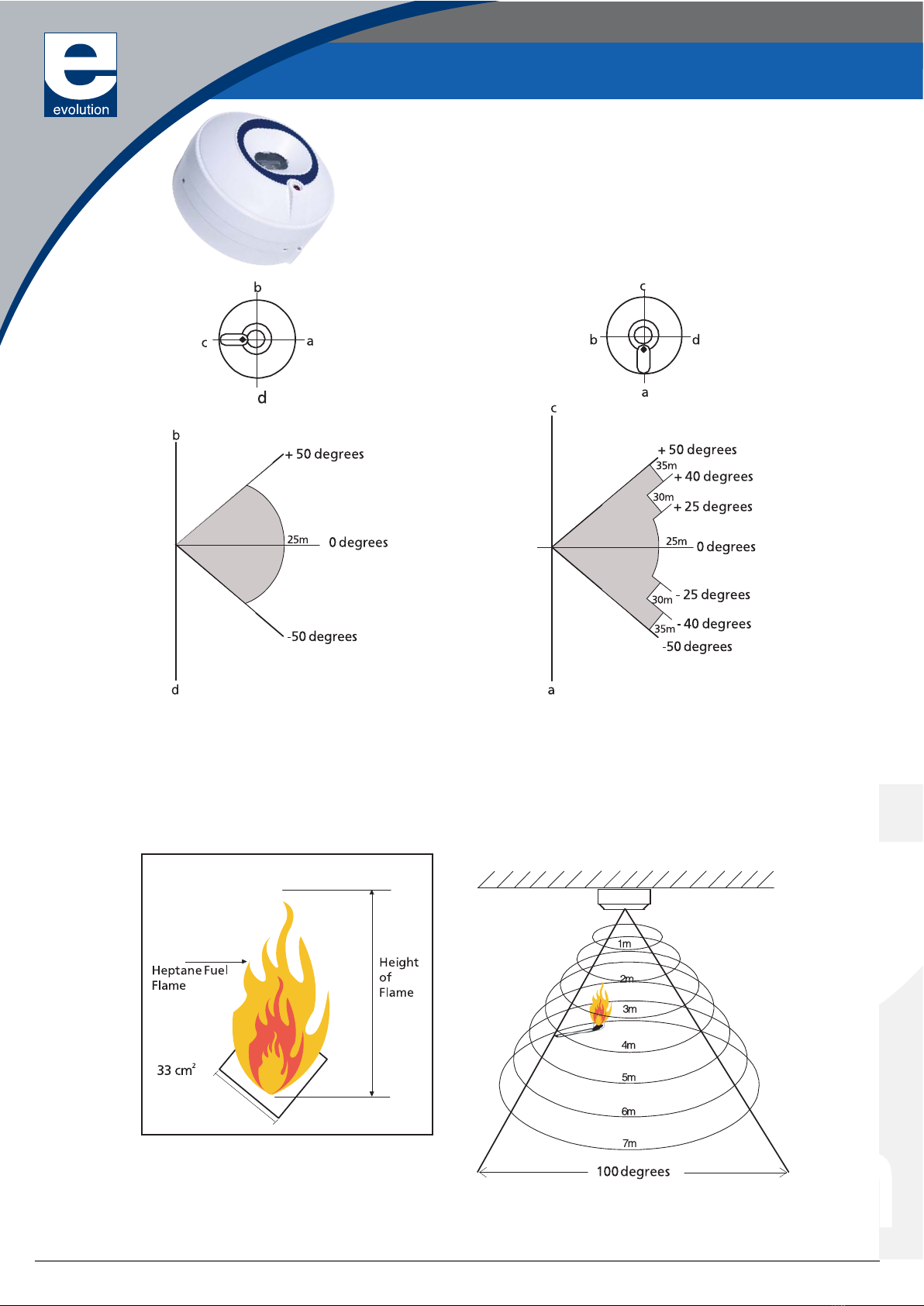
Sensitivity results have all been obtained
by testing theEV-UV with the following
flame size as below:-
The EV-UV sensor may be positioned in two ways. Each way determines the distance and area coverage
of a single detector.
Fig. 3. shows the EV-UV in the B-D position, and Fig. 4. shows the EV-UV in the C-A position. In both
examples, the shaded area indicates the actual detection area achieved for each positioning of
the sensor. The examples are based on tests carried out using a fuel fire covering an area of
approximately 33 square centimetres. (See Fig. 5.)
Fig. 6. demonstrates how the area of coverage of
the EV-UV sensor increases the further away
from the sensor head you go. The sensor
has a maximum detection angle of 100 degrees.
FIG. 3. FIG. 4.
FIG. 5.
FIG. 6.
• Ref No: NISM/EV-UV/01 • Date: 16.04.09 • Issue: 1
• evolution advanced • EV-UV • analogue addressable ultraviolet flame sensor
instruction manual
Tabla de contenidos
Otros manuales de Sensor de seguridad de Nittan


