Nice FLOR Series Manual de usuario

V. 003
Radiocomando
serie FLOR e
VERY
ricevitori
modulari
FLOXMR
FLOXM220R
Manuale di
istruzioni per
l’installazione
FLOR and
VERY Radio
control series,
modular
receivers
FLOXMR
FLOXM220R
Installation
instruction
manual
Radiocommande
série FLOR et
VERY
récepteurs
modulaires
FLOXMR
FLOXM220R
Manuel
d’instructions
pour l’installation
Funksteuerung
Serie FLOR
und VERY
Modulare
Empfänger
FLOXMR
FLOXM220R
Installation-
sanleitungen
Radiocontrol
serie FLOR y
VERY
receptores
modulares
FLOXMR
FLOXM220R
Manual de
instrucciones
para la instalación

English

INTRODUCTION
When a radio control system is used the transmitter sends a “signal” to the receiver that, if recognised
as valid, activates the output relays.
In view of the fact that a transmitter should activate only its own receiver and not that of your
neighbour, you have to codify the signal sent which means that each receiver will recognise its own
signal and not others that might be similar.
In traditional systems the code can be selected by means of a set of microswitches in the transmitter
(offering only a few thousand combinations) or it can be programmed directly during production (in
this case you have a few million different code numbers available); however, the code number is
fixed which means that each time it is transmitted the same signal is sent.
The fact that the code is sent by radio and that it is always the same does, unfortunately, offer the
possibility to people who are up to no good to receive (even at a distance) and record the signal
which they can then use as the “key” to open your door.
The “FLOR” system uses a principle that makes your radio control extremely safe.
A technique called “Rolling Code” is used that changes a part of the code each time it is transmitted
following a predefined sequence; the code is masked with appropriate mathematical functions so
there is no logical connection between two consecutive codes. The receiver is always synchronised
with the transmitter so it will accept only the programmed code sequence. It is completely useless to
try and copy the signal transmitted with this system because once the code has been “used” the
- 30 -

receiver will only recognise the next one.
From what we have described here it appears essential to keep the code sent by the transmitter and
the receiver perfectly synchronised but this is not completely true because there is a code window
that lets the receiver accept, in sequence, the next code plus a certain number of subsequent codes
without ever accepting a code that has already been used!
Even if you exit from the code window, the receiver is designed to re-synchronise itself automatically:
when it receives the first code there will be no activation but only storage of the code sent; when the
next signal is sent it will be synchronised and activate the outputs. Automatic re-synchronisation is of
course possible only if the codes are received following the established sequence.
DESCRIPTION
The “FLOR” system comprises:
• 1, 2 or 4 channel transmitters (FLO1R, FLO2R, FLO4R) and 2 channel (VR of the VERY series)
• Modular receivers (FLOXMR, FLOXM220R)
• Receivers with a terminal connection, 1 or 2 channels (FLOX1R, FLOX2R, FLOXB2R)
• Receivers with plug in connections, 1 or 2 channels (FLOXIR, FLOXI2R)
• Memory card that contains the codes (BM60, BM250, BM1000 - 15, 63 or 255 codes maximum
respectively)
• Aerial (ABF - ABFKIT)
- 31 -
GB

INSTALLATION
Transmitters:
The transmitters are ready to use, each with their own code number set during construction. To see
if they are working properly simply press one of the keys and check that the red LED is flashing which
indicates transmission.
The transmitter has a device built into it that controls battery state: press one of the keys and if the
battery is fully charged, the LED will give an initial pulse followed immediately by the transmission
signal. If the battery is partly flat the
LED will give the first pulse and start
transmitting only after half a second.
In this case we advise you change the
battery as soon as possible.
On the other hand, if the battery is
completely flat the LED will flash at
half-second intervals without
transmitting and the battery must be
changed immediately.
- 32 -
VERY FLO1R FLO2R FLO4R
LED
KEY 1
KEY 2
KEY 3
KEY 4
LED
KEY 1
KEY 2
Fig. 1
Selecting the channel on the transmitter:
It is possible to modify the key-channel connection on the FLOR1 and FLOR2 versions.
For key 1, simply cut the track that linked it to the 1st channel, as shown in Fig. 1A, and connect one
of the other pads on the right with a drop of solder to link it to the 2nd, 3rd or 4th channel. Do exactly
the same for the 2nd key, as shown in Fig. 1B. On VR the transmitters in the VERY series, the
key/channel association cannot be modified.
- 33 -
GB
WELDING
SIDE Fig. 1A
1
ST
KEY 2
ND
KEY
cut
cut
1
st
channel
1
st
channel
2
nd
channel
2
nd
channel
3
rd
channel
3
rd
channel
4
th
channel
4
th
channel
Fig. 1B

Modular receivers
Modular receivers, with 12-24 Vac-dc (FLOXMR or 220 Vac (FLOXM220R) power, will let you control
up to 4 channels, also simultaneously, and to manage up to 1020 code numbers. Wire up following
this sequence: 1-2: POWER: from 10 to 28 Vac-dc
(FLOXMR) with jumper. 220 Vac
(FLOXM220R).
3-4: 1st RELAYOUTPUT: free
contact of a normally open relay.
5-6: 2nd RELAY OUTPUT: free
contact of a normally open relay.
7-8: 3rd RELAY OUTPUT:
free contact of a normally open
relay.
9-10: 4th RELAY OUTPUT:
free contact of a normally open
relay.
1-2: AERIAL:
aerial signal input.
- 34 -
CH.1
CH.1
CH.1
CH.1
345678
1. 2. 3. 4.
OUTPUTS
FLOXM220R = 220Vac
FLOXMR = 12 - 24 Vcc/ca AERIAL
18 - 28 V
10 - 18 V
(FLOXMR only)
Fig. 2

Memory card
Each transmitter has its own code number (selected from more than 250 million) that distinguishes it
from all other remote controls. The receiver can receive all the codes but is activated only if that
particular code is on the list of “authorised” code numbers on the memory card.
The receivers are supplied with a BM1000 memory card that can contain a maximum of 255 code
numbers (255 remote controls are the maximum quantity). A BM60 memory card can also be used
with a maximum of 16 code numbers or a
BM250 with a maximum of 63 code
numbers.
Other memory cards can be plugged in if
required up to a maximum of 4 and,
hence, a total of 1020 code numbers. The
cards must be plugged-in in order, from
the 1st to the 4th. The receiver does, in
fact, enter and search codes starting from
the first memory card and then goes on to
the second if necessary, and so on. If a
memory card is not completely full or is
completely missing, the subsequent
memory cards are disregarded.
- 35 -
GB
1°
2°3°4°
Fig. 3

The memory cards must always be of the same type.
When the receiver is turned on it displays the type of memory card being used. If it is a BM60, the
LED will flash briefly. If it is a BM250 the LED will flash twice while if it is an BM1000 the LED will
flash three times.
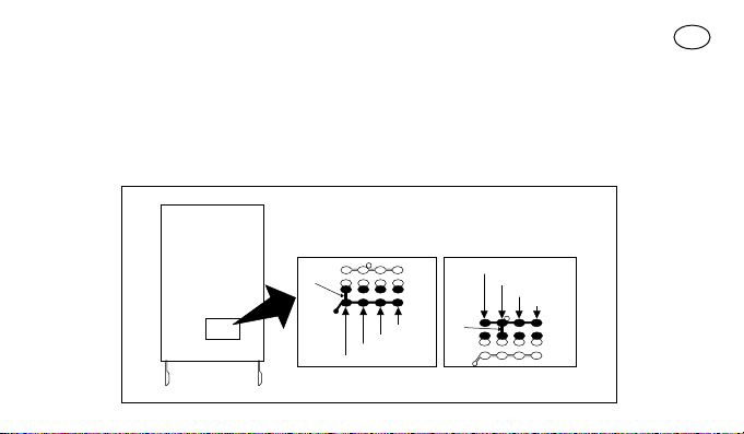
All the codes are stored in the memory, so when maximum security is required the code learning
function must be disabled (this can also be done remotely). After the code numbers of the remote
controls being used have been entered, break the track indicated by an arrow (Fig. 4). If, later on,
you wish to enter other code numbers, join the two pads with a dot of solder (Fig. 5)
ATTENTION!!: Turn the receiver off before pulling out or plugging in a memory card
- 36 -
051A LS
051A LS
Fig. 4 Fig. 5
CUT JOIN

This is a “hardware” type of disabling function, very simple to do but, consequently, very easy
to undo by an intruder.
There is also another type of disabling function, a “software” type, more difficult to manage but
extremely secure in that only a previously authorised remote control can be used to restore it (see
activating/deactivating the 2nd disabling function).
Still on the subject of safety, there is another even more secure type of disabling function, which is
controlled by a “PASSWORD”. Only a portable accessory BUPC manages this function.
ADJUSTMENTS AND SETTINGS
Selection of the relays on the channels
Each receiver can recognise all 4 transmitter channels, also simultaneously.
Association of the channel to the relay is fixed and depends on the relay’s position. Different types of
relay modules can be plugged into the connectors which differ in the kind of function they perform.
In the normal functioning mode the relay in output is a temporary type, that is, it is energised a few
seconds after the transmitter key has been pressed (delay due to code recognition time) and it de-
energises 300mS after the key has been released.
- 37 -
GB
Este manual sirve para los siguientes modelos
3
Tabla de contenidos
Otros manuales de Mando a distancia de Nice

Nice
Nice SMILO Series Manual de usuario

Nice
Nice RGBW-Control Especificaciones técnicas

Nice
Nice planotime Manual del producto

Nice
Nice ECCO5 Manual de usuario

Nice
Nice Oview Manual de usuario

Nice
Nice NX FIT MB 534 SH BD Especificaciones técnicas

Nice
Nice MIGHTY MULE MMT103 Manual de usuario

Nice
Nice DS100 Especificaciones técnicas

Nice
Nice TX FLOR-S Manual de usuario

Nice
Nice Era INTI1 Manual de usuario


