NI TB-414X Manual de usuario
USER GUIDE
TB-414X
Screw Terminal Connector Kit for PXIe-414x SMUs
This document explains how to install and use the TB-414X terminal block with a PXIe-414x
source measure unit (SMU) and includes TB-414X specifications.
The TB-414X terminal block is used to convert the 25-position D-SUB connector of the
PXIe-414x SMU to screw terminal connections while maintaining low leakage performance.
Read this document before you install, configure, operate, or maintain this product. Users are
required to familiarize themselves with installation and wiring instructions in addition to
requirements of all applicable codes, laws, and standards. Visit ni.com/manuals for more
information about your product, including specifications, pinouts, and instructions for
connecting, installing, and configuring your system.
Caution Observe all instructions and cautions in the user documentation. Using
the product in a manner not specified can damage the product and compromise the
built-in safety protection.
Attention Suivez toutes les instructions et respectez toutes les mises en garde de la
documentation d'utilisation. L'utilisation du produit de toute autre façon que celle
spécifiée risque de l'endommager et de compromettre la protection de sécurité
intégrée.
Notice This device is intended for use only with the PXIe-4140, PXIe-4141,
PXIe-4142, PXIe-4143, PXIe-4144, PXIe-4145, and PXIe-4147 SMUs, which are
referred to collectively as PXIe-414x SMUs. For more information about the
PXIe-414x SMUs, refer to ni.com/manuals.
Contents
Icons.......................................................................................................................................... 2
Getting Started with the TB-414X............................................................................................ 2
Kit Contents and Other Equipment...................................................................................2
Installing the TB-414X..................................................................................................... 3
TB-414X Specifications............................................................................................................7
Definitions.........................................................................................................................7
Voltage, Current, and Resistance...................................................................................... 8
Isolation.............................................................................................................................9
Screw Terminal Wiring..................................................................................................... 9

Physical........................................................................................................................... 10
Environmental Guidelines...............................................................................................10
Compliance and Standards...................................................................................................... 11
Safety Compliance Standards..........................................................................................11
Environmental Management........................................................................................... 11
CE Compliance .............................................................................................................. 12
Export Compliance......................................................................................................... 12
Product Certifications and Declarations......................................................................... 12
Additional Resources.............................................................................................................. 12
NI Services..............................................................................................................................13
Icons
Notice Take precautions to avoid data loss, loss of signal integrity, degradation of
performance, or damage to the model.
Caution Take precautions to avoid injury. Consult the model documentation for
cautionary statements when you see this icon printed on the model. Cautionary
statements are localized into French for compliance with Canadian requirements.
Getting Started with the TB-414X
Kit Contents and Other Equipment
Your kit includes an assembled TB-414X. In addition, you will need the following items not
included in your TB-414X kit to install and use the TB-414X.
• PXIe-414x
• 24 to 18 AWG signal wires
• Number 1 Phillips-head screwdriver
• 2.5 mm (3/32) flathead screwdriver
• Wire insulation strippers
• Wire cutters
Visit ni.com for more information about the PXIe-414x. Refer to the Additional Resources
section for a list of related documentation for your device.
2| ni.com | TB-414X User Guide

Installing the TB-414X
Complete the following steps to install the TB-414X with a PXIe-414x and prepare signal
connections.
Before you begin, install the PXIe-414x in a chassis and ensure that all signals are
disconnected from the PXIe-414x if you have not already done so. Refer to the getting started
guide for your module at http://www.ni.com/manuals for installation instructions.
Note Maintaining low leakage performance of the SMU and TB-414X requires
careful selection and termination of the external wiring to ensure guarding of the HI
and HI Sense signals and to minimize negative effects from wiring insulation
materials and contaminants. The SHDB25F-DB25F-LL cable accessory has been
designed with these considerations in mind and utilizes the TB-414X, allowing for
one end to be easily reterminated into an alternate connector, if needed.
Note NI recommends wearing clean gloves during assembly to avoid
contamination from residues or other debris.
1. Prepare the wires by stripping the insulation 5 mm to 6 mm (0.197 in. to 0.236 in.) from
one end of all wires.
Use signal wires with a wire gauge of 24 to 18 AWG.
2. Disassemble the TB-414X.
a) Unscrew the four screws on the top of the TB-414X to remove the top cover.
b) Unscrew the two screws securing the strain relief to remove the strain relief.
TB-414X User Guide | © National Instruments Corporation | 3

Figure 1. Disassembled TB-414X
3. Connect the signal wires and ground/shield wire by inserting the stripped end of the wires
into the appropriate terminals and tighten the screws of the screw terminals to a torque of
0.5 Nm (4 lb · in.).
Refer to the following pinout, signal information, and PXIe-414x pin map to make the
appropriate connections for your application.
4| ni.com | TB-414X User Guide

Figure 2. TB-414X Pinout
CH 0 LO -
CH 0 LO S -
CH 1 LO -
CH 1 LO S -
CH 2 LO S -
CH 2 LO -
CH 3 LO S -
CH 3 LO -
-
GUARD -
HI -
HI S -
CH 0
HI S -
HI -
GUARD -
CH 3
GUARD
HI
HI S
HI S
HI
GUARD
CH 1
CH 2
Table 1. TB-414X Signals and DB25 Pin Map
Screw Terminal DB25 Connector Pin
LO Connector
CH 0 LO 16
CH 0 LO S 3
CH 1 LO 19
CH 1 LO S 6
CH 2 LO 22
CH 2 LO S 9
CH 3 LO 25
CH 3 LO S 12
CH S GND Shield
CH 0 Connector
CH 0 GUARD 1
CH 0 HI 14
CH 0 HI S 2
CH 1 Connector
CH 1 GUARD 4
CH 1 HI 17
CH 1 HI S 5
TB-414X User Guide | © National Instruments Corporation | 5
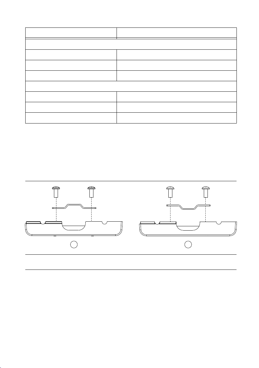
Table 1. TB-414X Signals and DB25 Pin Map (Continued)
Screw Terminal DB25 Connector Pin
CH 2 Connector
CH 2 GUARD 7
CH 2 HI 20
CH 2 HI S 8
CH 3 Connector
CH 3 GUARD 10
CH 3 HI 23
CH 3 HI S 11
4. Reassemble the TB-414X.
a) Bundle the wires together under the strain relief and install the strain relief by
tightening the two screws removed in previous steps to a torque of
0.3 Nm (2.7 lb · in.).
• If you are connecting several wires, assemble the strain relief upward.
• If you are connecting only a few wires, assemble the strain relief downward for
greater retention.
Figure 3. TB-414X Strain Relief
1 2
1. Strain Relief Up
2. Strain Relief Down
b) Install the top cover of the TB-414X by tightening the four screws removed in
previous steps to a torque of 0.3 Nm (2.7 lb · in.).
5. Connect the TB-414X to the PXIe-414x.
a) Align the female D-SUB connector on the back of the TB-414X and the male D-
SUB connector on the front of the PXIe-414x and attach.
b) Tighten the thumbscrews on the front of the TB-414X until the terminal block is
secured to the PXIe-414x.
6| ni.com | TB-414X User Guide

Figure 4. Installed TB-414X
To uninstall the TB-414X, loosen the thumbscrews on the front of the TB-414X and detach the
terminal block from the front of the PXIe-414x.
TB-414X Specifications
These specifications apply to the TB-414X for use with the PXIe-414x.
The PXIe-414x is a 4-Channel SMU. Refer to the module specifications at ni.com/manuals for
more information.
Definitions
Warranted specifications describe the performance of a model under stated operating
conditions and are covered by the model warranty.
TB-414X User Guide | © National Instruments Corporation | 7

Characteristics describe values that are relevant to the use of the model under stated operating
conditions but are not covered by the model warranty.
•Typical specifications describe the performance met by a majority of models.
•Nominal specifications describe an attribute that is based on design, conformance testing,
or supplemental testing.
Specifications are Warranted unless otherwise noted.
Voltage, Current, and Resistance
Notice Refer to the specifications of the module with which you are using the
TB-414X to note the maximum voltage and current ratings. The specifications listed
below are the maximum for the TB-414X only.
Channel operating voltage160 V DC
HI/LO pin current23 A
Note It is critical to ensure that the LO terminal for each channel in use is
connected when the total current from all channels exceeds 3 A. The TB-414X is
rated for the force pins carrying a maximum of 3 A average current, however,
individual pin currents above 4 A may damage or degrade the lifespan of the pins.
Systems that have a common path between the LO of each channel at the DUT end
of the cable must ensure that LO path wiring resistances are matched within ±20% to
prevent the LO terminal of one channel from carrying a significant portion of
another channel’s LO current and exceeding the 4 A individual pin limit.
Force path resistance330 mΩ, typical
Leakage resistance4
23 °C >100 TΩ, typical
1Maximum voltage measured between the HI, HI Sense, LO, LO Sense, or Guard terminals. SMU
specifications take precedence if the SMU model is rated for lower voltage.
2SMU specifications take precedence if the SMU model is rated for lower current.
3Combined resistance in the HI and LO force traces and connectors for a channel of the TB-414X.
Does not include any output resistance contributions of the SMU module or user wiring. Refer to
SMU module specifications to determine if this resistance is included in the voltage load regulation
specification or if it should be accounted for separately.
4Applies between HI and LO terminals. Leakage performance may be degraded for operation above
70% relative humidity. When transitioning a device from a storage or operation environment with
operating humidity above 70%, allow the device to stabilize in the lower humidity environment for
several hours before use.
8| ni.com | TB-414X User Guide
Isolation
Caution Isolation voltage ratings apply to the voltage measured between any
channel pin and the chassis ground. When operating channels in series or floating on
top of external voltage references, ensure that no terminal exceeds this rating.
Attention Les tensions nominales d'isolation s'appliquent à la tension mesurée
entre n'importe quelle broche de voie et la masse du châssis. Lors de l'utilisation de
voies en série ou flottantes en plus des références de tension externes, assurez-vous
qu'aucun terminal ne dépasse cette valeur nominale.
Caution Do not connect the TB-414X to signals or use for measurements within
Measurement Categories II, III, or IV.
Attention Ne connectez pas le TB-414X à des signaux et ne l'utilisez pas pour
effectuer des mesures dans les catégories de mesure II, III ou IV.
Measurement Category I is for measurements performed on circuits not directly connected to
the electrical distribution system referred to as MAINS voltage. MAINS is a hazardous live
electrical supply system that powers equipment. This category is for measurements of voltages
from specially protected secondary circuits. Such voltage measurements include signal levels,
special equipment, limited-energy parts of equipment, circuits powered by regulated low-
voltage sources, and electronics.
Note Measurement Categories CAT I and CAT O are equivalent. These test and
measurement circuits are for other circuits not intended for direct connection to the
MAINS building installations of Measurement Categories CAT II, CAT III, or
CAT IV.
Isolation voltage, channel to earth ground560 V DC, CAT I
Withstand voltage 800 Vpk
Screw Terminal Wiring
Screw terminal wire gauge 24 to 18 AWG
Length of bare wire (insulation stripped)
from one end of the wire
5 mm to 6 mm (0.197 in. to 0.236 in.)
Screw terminal torque 0.5 Nm (4 lb · in.)
Spacing between screw terminals 3.5 mm (0.14 in.)
5While TB-414X channels are isolated from each other, this isolation is considered functional
isolation for the purpose of allowing the separation of return currents and is not intended to operate
continuously under significant voltages or provide safety isolation. The TB-414X is intended for
use with PXIe-414x SMUs which are isolated from earth ground, but share a common LO for all
channels (bank isolation).
TB-414X User Guide | © National Instruments Corporation | 9

Figure 5. TB-414X Dimensions
75 mm
(2.9 in.)
19 mm
(0.8 in.)
18 mm
(0.7 in.)
12 mm
(0.5 in.)
90 mm
(3.5 in.)
112 mm
(4.4 in.)
Physical
Top cover and strain relief screws #4-40
Top cover and strain relief screw torque 0.3 Nm (2.7 lb · in.)
Dimensions 112 mm × 74 mm × 19 mm
(4.4 in. × 2.9 in. × 0.8 in.)
Weight 112 g (3.95 oz)
Environmental Guidelines
Notice This model is intended for use in indoor applications only.
Environmental Characteristics
Temperature and Humidity
Temperature
Operating 0 °C to 55 °C6
Storage -40 °C to 71 °C
6Not all chassis can achieve this ambient temperature range. Refer to PXI chassis specifications to
determine the ambient temperature ranges your chassis can achieve. SMU specifications take
precedence if the SMU model is rated for different operating temperatures.
10 | ni.com | TB-414X User Guide
Tabla de contenidos
Otros manuales de Bloque de terminales de NI


Manuales populares de Bloque de terminales de otras marcas


Hubbell
Hubbell BASETRAK PB2 Series Manual de usuario

Crestron
Crestron CLT-2DIM2 Manual de usuario

Omron
Omron XW2B-40J6-2B Manual de instrucciones

Festo
Festo CPV GE-IL Series Manual de lista de piezas

Lenz
Lenz XpressNet Digital plus LA152 Manual del propietario

National Instruments
National Instruments BNC-2120 Manual de usuario