7
Ness - IDTECK
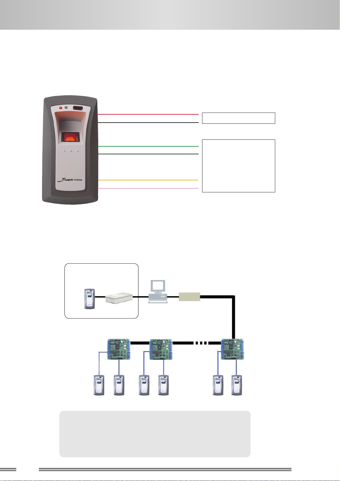
2.W IRING & INITIAL SETTING
2-7-2. Ness FINGER007 Initial Setting
FINGER_007 [F1]
MM/DD HH:MM:SS
Start Display Enter into
Setup Mode
Enter
Master No
(Default : 00000000)
Enter Master
P/W
(Default : 3141)
MODE SELECTION
RF + FINGER(P/W)
MODE SELECTION
RF + FINGER(P/W)
Display for Mode Selection
ENT MODE SELECTION
->RF + FINGER(P/W)
COMM ID SETTING
Display for Mode Selection
ENT COMM ADDRESS
00
ID REGISTRATION
Put ID CARD
Scanning ...
Key InPut ID
->_ _ _ _ _ _ _ _
To Register FP
Put Your FP On ...
Display for ID Registration
Display for Finger registration Display for finishing
ENT
1
2
Enter
Finger 2
times
CARD & Key Use
1-Card, 2-Key
CARD & Key Use
1-Card, 2-Key
12345678
PW0000TS00RD3FP1
ID Registed
ID DELETE ENT Enter Card No.
-> _ _ _ _ _ _ _ _
4 or 6 key : Left / Right MOVE
2 or 8 key : Up / Down MOVE
ENT : OK or Enter
ESC : Cancel or deactivate
RF Only : Card
RF + FINGER(P/W) : Card + Finger(P/W)
RF + P/W + FINGER : Card + P/W + Finger
Press Ent under COMM ADDRESS status and enter
address No(00 ~ 31)
1 - Card : Register card & fingerprint
2 - Key : Register PIN(4~8 digit) & fingerprint
Caution : Present finger on scan window closely and
press softly to make sure that the fingerprint is
positioned correctly
Present card or enter 4~8 digit No. intended to
delete (In case of 4 digit No. Enter ‘0000’ before
the No to make it 8 digit No.)
Ent 1:Present Card, Ent 2 :Enter PIN(4~8 digit)
PW:Enter P/W
~ Will be used under P/W mode
TS: Set Time Schedule
~ Set accessible time
RD: Set Reader mode
1 ~ Use only main device
2 ~ Use only exit reader
3 ~ Use both reader
FP: Use/Not use Fingerprint
(1:Use, 0:Not use)
a. SET MODE SELECTION (Select mode with 4 or 6 Key)
b. SET ADDRESS (Select mode with 4 or 6 Key, Enter Address from Numeric Key)
c. CARD & FINGER REGISTRATION (F3 KEY)
d. DELETE CARD & FINGERPRINT (Enter F3, Search with 4 or 6)
Display for ID delete
e. Hardware Initialization. (In case master card or ID is lost)
1. Please check if the back-up battery dip switches are on the
backside of the device as the picture. If not, please set them on. 2. Connect three wires of pink, cyan and black color and
turn the power on
3. A message of “system initialization” is to be shown in LCD
4. Press “1” to choose “Yes” and enter desault master P/W
(3141) then “system initialization completed” message is to
show in the LCD
5. Disconnect those three wires and wire them as normal
connection diagram as before
SETTING A DIP SWITCH
Before After
OFF ON
1212