NCD Gen3 Ethernet Module Manual de usuario

G
EN
3
E
THERNET W
/N-B
UTTON
Push Notification Quick Start Guide
Na t i o na l C o n trol D e v i c e s

R E L A Y P R O S
1
Introduction
Real-Time Status Control
Ethernet Push Notification Board that allows you to connect a dry contact (no
voltage) to the oard and send an email or text message when the circuit is
closed. The oard will communicate the contact closure information to your
computer through a Ethernet connection. N-Button Software will then send a
text or email from the computer to your selected
recipients.
All the Features You Need…
•Send SMS or Email Message
•Compati le with ANY Contact Closure Sensor
Dry Contact (no voltage) input
•On oard Ethernet Interface Module
Communicate over your network
•N-Button Software
Point & Click Interface
Use to Configure Messages
Step-By-Step Instructions
This Manual will give you step- y-step instructions for connecting your
Ethernet Push Notification Board and setting up N-Button Software to send
text and/or emails.
Chapter
1

R E L A Y P R O S
2
[Date]
Important Details
DHCP
By default, NCD Gen 3 modules ship in DHCP mode so it is expected that they e
connected to a DHCP ena led networks. Most routers support DHCP, however if
your network does not support DHCP then you will want to store a static IP
address into the controller.
Force Static IP for Configuration
If your network does not support DHCP then power down the main control
oard. Install a jumper on the two pins directly to the left of the Ethernet Jack
then power the oard up again. Installing a jumper on these two pins will force
the module to use a Static IP address of 192.168.1.88. This will allow you to
connect to the Gen 3 Module for configuration on a Non DHCP ena led network
or y connecting the Ethernet module directly to the Ethernet port of your
PC. When configuring settings in this way you will need to leave the static IP
address jumper in place, alter the settings, select “Apply Settings”, power down
the control oard, wait 2 seconds, remove the static IP jumper, and power the
oard ack up for the settings to e stored in the module.
Factory Reset
There is a hardware method of restoring the Gen 3 module to factory default
settings. To do this press and hold the utton to the right of the Ethernet Jack for
5 seconds, then release the utton. This will factory reset all setting inside the
Gen 3 module.
Note
Always connect the Ethernet ca le to the Gen 3 module and the network prior to
powering the oard up.
Applying Settings
Any time settings are altered on the Gen 3 module it is necessary to power cycle
the module. This can e done y manually removing power from the host oard
or y clicking the Reset utton in the software/we interface.
Chapter
2

R E L A Y P R O S
3
[Date]
Base Station Software
Base Station Software is our reference tool for designing and testing all
currently manufactured NCD Devices. Base Station will assist you in
learning how any NCD device functions and will provide valua le
diagnostic tools to help determine if your controller is functioning as
designed. Base Station software exercises every supported feature of every
supported device. It is the ultimate reference tool for learning, diagnosing,
and testing NCD devices.
Discovered Network Devices
Base Station will
discover the Ethernet
oard on the network
and show you the IP
address assigned to the
oard. Select
Discovered Network
Devices utton then
click on the IP Address,
this will open your
rowser and show you
the We Interface
Connection and all its
features. By selecting
the Discovered
Network Devices utton then clicking OK, Base Station Software will open
showing you the command sets that are availa le for your oard.
Device Co and Sets
Base Station software asks the controller which command sets are
supported. The supported command sets are listed when you run the Base
Station software application. Some controllers may show more command
sets while other controllers may show fewer command sets. The Base
Station program will decide which command sets apply to your oard.
Make sure you shut down Base Station efore running N-Button Software.
N-Button may not connect to the oard if Base Station is already
connected.

R E L A Y P R O S
4
[Date]
Web Interface Connection
Gen 3 modules have a uilt-in we interface which may e
utilized to configure settings in the module
To access the we
interface simply open
your we rowser and
enter the IP address of
the Gen 3 module. If
you do not know the
module’s IP address you
may e a le to discover
it y opening the Base
Station or Alpha Station
software. It is also
possi le to o tain the
module’s IP address y
checking the DHCP
Ta le of your Router. If
your router does not
support DHCP simply
power the oard down
and install a jumper on
the pins directly to the left of the Ethernet Jack, then power the oard ack
up. This will force the module to use a static IP address of
192.168.1.88. Note however that the module will not utilize user
configured settings while this jumper is installed so e sure to power down
the oard and then remove the jumper once settings are entered as
desired.
Default Password
The We interface is password protected. The default password for the
we interface is ad in.
Device View
The Device View page displays current information a out the Gen 3
Module such as its network connection information, its socket mode
information, UART Settings, etc.

R E L A Y P R O S
5
[Date]
Basic Settings
Most settings you will e interested in configuring can e found under
Basic Settings. Here you can configure A static IP address and the type of
socket connection the module should utilize. Here we will review each of
these settings.
Use DHCP
If this ox is checked
the module will o tain
an IP Address from
your DHCP server on
the network router. If
this ox is checked the
IP Address, Su net
Mask, Gateway, and
DNS Server fields will
e ignored. If you
intend to enter Static
IP address settings
make sure this ox is
NOT checked.
IP Address
This setting is only
applica le if Use DHCP
is unchecked. This
field configures the Static IP address the module should utilize on the
network.
Subnet Mask
This setting is only applica le if Use DHCP is unchecked. This field
configures the Su net Mask the module should use on the Network it is
connected to.
Gateway
This setting is only applica le if Use DHCP is unchecked. This field should
match the IP address of your network router.
DNS Server
This setting is only applica le if Use DHCP is unchecked. This field will
configure the DNS Server the Module uses for DNS requests.

R E L A Y P R O S
6
[Date]
Start Mode
This field configures the mode the module should utilize on oot. For NCD
Devices only Data Mode is recommended.
Socket Type
TCP Server MUST BE SELECTED.
If you change this setting from UDP or TCP Client setting, power cycle the
board before trying to connect to N-Button oftware. This field configures
how the module handle’s socket connections. The options are TCP Server,
TCP Client, or UDP. In TCP Server mode the module will oot up and egin
listening for socket connections from software applications
Re ote Host
This field is only applica le when Socket Type is set to TCP Client or
UDP. This field configures the IP address the module should attempt to
esta lish a connection to on start up.
Re ote Port
This field is only applica le when Socket Type is set to TCP Client or
UDP. This field configures the Port the module should attempt to esta lish
a connection to on start up.
Local Port
This field is only applica le when Socket Type is set to TCP Server. This
field configures the Port the module will accept TCP client connections on.
UART Setting
These fields configure how the module handles serial communication with
the main control oard it is plugged into. NCD Staff test and configure
every module prior to shipment so all of these settings should e correct
when you receive your product. If any changes are made to these settings
it will e necessary to make configuration settings to the main host control
oard the module is installed in as well.
Save Settings/Reset
Once settings are entered and configured as desired click the Save Settings
Button. This will store settings into the Gen 3 module, however these new
settings will not e utilized until the next power up of the module so if you
would like to implement the new settings now click the Reset utton after
clicking the Save Settings Button.

R E L A Y P R O S
7
[Date]
Advanced Options
When setting up the push notification oard there isn’t any settings in the
Advanced Ta that need to e changed. For an overview on the Advanced
Options ta , download the full Gen3 Ethernet Quick Start Guide at:
relaypros.com/start.htm.
Manage ent
Password Setting
The We interface is
password protected. The
default password for the
we interface is
ad in. If desired, you
may change this
password using the
Password Setting
Fields. After the new
password is set it will
take effect after the next
power cycle.
Factory Default
It is possi le reset the
Gen 3 module to factory
default settings y
pressing this Default
Button
Reset Device
It is possi le to power cycle the Gen 3 Module y pressing this Reset
Button.
Logout
This utton will log the user out of the we interface. Keep in mind
password changes will not take effect until a power cycle to the module.

R E L A Y P R O S
8
[Date]
N-Button Communication and
can Channel etup
N-Button
Communicating to the Board
1.
Download and install the version of N-Button Pro or N-Button Lite that
you purchased with the oard.
Open N-Button Then Click Device Manager –> You must add the oard
to the device list. You will use this device for each input on the oard.
R E L A Y P R O S
9
[Date]
Na e –> You can assign a name to the oard. This will e important if
you have more than one oard on the network.
Manufacturer –> National Control Devices
Board Type –> Push Notification
IP Address/Mac Address –> The device should e listed in the Discovered
Devices area. Once it is, dou le click the IP Address and the IP Address,
and Mac Address will populate the Network area a ove.
TCP/UDP Port –> Keep default setting for TCP Port (2101) and UDP Port
(3333).
TCP Connection –> Check the TCP Connection check ox.
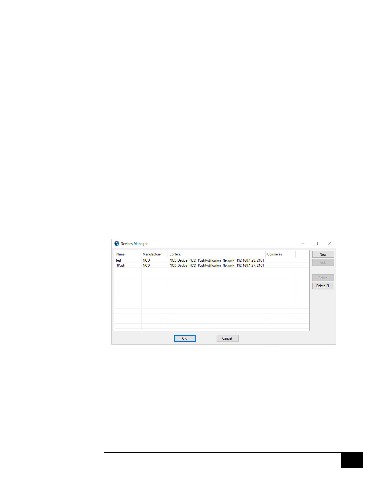
Click OK to save the device –> The device will now e in the
device manager. Dou le clicking this device in Device Manager will allow
you to edit and make changes to the device. The screen shot elow has two
devices installed, you can have more than one device on the network with
N-Button.
Otros manuales para Gen3 Ethernet Module
1
Tabla de contenidos
Otros manuales de Hardware de red de NCD


Manuales populares de Hardware de red de otras marcas

Matrix Switch Corporation
Matrix Switch Corporation MSC-HD161DEL Manual de usuario

B&B Electronics
B&B Electronics ZXT9-IO-222R2 Manual de usuario

Yudor
Yudor YDS-16 Manual de usuario

D-Link
D-Link ShareCenter DNS-320L Manual de usuario

Samsung
Samsung ES1642dc Instrucciones de uso

Honeywell Home
Honeywell Home LTEM-PV Instrucciones de montaje


