Nagel 2S Trimmer Manual de usuario
2S Trimmer
Service Manual
Nagel 2S Trimmer

© Ernst Nagel GmbH 2S Trimmer Service Manual en.doc Rev.1.0. 20.07.2011
2
PAGE INTENTIONALLY BLANK

© Ernst Nagel GmbH 2S Trimmer Service Manual en.doc Rev.1.0. 20.07.2011
3
Contents
TITLE PAGE
CONTENTS....................................................................................................................................................... 3
1. SAFETY..................................................................................................................................................... 5
2. GENERAL.................................................................................................................................................. 6
2.1 BASIC INFORMATION ................................................................................................................................... 6
2.1.1 Basic Information............................................................................................................................... 6
2.1.1 Type of machine and TAG ................................................................................................................ 7
2.2 GETTING TO KNOW THE STR....................................................................................................................... 8
2.2.1 Main components overview............................................................................................................... 8
2.2.2 Components overview Inside............................................................................................................ 9
2.2.2 Components overview Inside.......................................................................................................... 10
2.2.3 Components overview Interlock breaker & Safety block for knife beam......................................... 13
2.2.4 Components overview I-CAN plug & Mode Selection plug............................................................. 14
2.2.5 Rollers and Belts ............................................................................................................................. 15
2.2.6 Interface signals explanation........................................................................................................... 18
3. GLOBAL FUNCTIONALITY DESCRIPTION.......................................................................................... 19
3.1 BYPASS MODE .......................................................................................................................................... 20
3.2 TRIMMING MODE ....................................................................................................................................... 24
4. COVERS.................................................................................................................................................. 29
4.1 FRONT COVER ......................................................................................................................................... 29
4.2 REAR COVER ........................................................................................................................................... 30
4.3 UPPER INFEED COVER.............................................................................................................................. 31
4.4 LOWER INFEED COVER ............................................................................................................................. 32
4.5 UPPER OUTFEED COVER .......................................................................................................................... 33
4.6 LOWER OUTFEED COVER.......................................................................................................................... 34
4.7 BASE PLATE COVER ................................................................................................................................. 35
4.8 USER INTERFACE COVER .......................................................................................................................... 36
5. TROUBLESHOOTING............................................................................................................................. 37
5.1 SERVICE PROGRAM MODE......................................................................................................................... 37
5.1.1 Software Version............................................................................................................................. 38
5.1.2 Diagnostics...................................................................................................................................... 39
5.1.3 Motors.............................................................................................................................................. 40
5.1.4 Solenoids......................................................................................................................................... 41
5.1.5 Sensors and Switches..................................................................................................................... 42
5.1.6 Voltmeters ....................................................................................................................................... 43
5.1.7 Non Volatile Memory (NVM)............................................................................................................ 44
5.1.8 Dead cycle....................................................................................................................................... 45
5.1.9 Calibration ....................................................................................................................................... 46
5.2 FAULT CODE DESCRIPTIONS ..................................................................................................................... 47
5.3 FAULT CODE SOLUTIONS .......................................................................................................................... 49
6. DEFAULT / BASIC ADJUSTMENTS...................................................................................................... 80
6.1 REPLACING KNIVES .................................................................................................................................. 80
6.1.1 Preparation...................................................................................................................................... 80
6.1.2 Removal Upper Knife...................................................................................................................... 81
6.1.3 Removal Lower Knife...................................................................................................................... 82
6.1.4 Placement Lower Knife ................................................................................................................... 83
6.1.5 Placement Upper Knife ................................................................................................................... 84
6.1.6 Adjustment Upper Knife .................................................................................................................. 85
6.1.7 Adjustment Lower Knife .................................................................................................................. 86

© Ernst Nagel GmbH 2S Trimmer Service Manual en.doc Rev.1.0. 20.07.2011
4
6.1.8 Spine Support Knives...................................................................................................................... 88
6.1.9 Testing / Finishing Adjustments ...................................................................................................... 89
6.2 ADJUSTING BOOKLET QUALITY ................................................................................................................... 90
6.2.1 Trapezium / Diamond Shape........................................................................................................... 91
6.2.2 Side Trim (Finished Size)................................................................................................................ 95
6.3 SENSORS AND SWITCHES ......................................................................................................................... 96
6.3.1 Replace Photo Sensors................................................................................................................... 96
6.3.2 Adjusting Photo Sensors................................................................................................................. 99
6.3.3 Replace Switches.......................................................................................................................... 102
6.3.4 Adjusting Switches........................................................................................................................ 103
6.4 REPLACING /PREPARING SIDE JOGGERS................................................................................................. 108
6.5 ADJUSTING SIDE JOGGERS ..................................................................................................................... 110
6.6 ADJUSTING CHAINS AND SPROCKETS ...................................................................................................... 112
6.7 MOTOR AND ENCODER POSITIONS ........................................................................................................... 115
6.8 TAPPING TRANSFORMER AND BLOWN FUSE CONDITIONS........................................................................... 116
6.9 ADJUSTING THICKNESS DETECTION ......................................................................................................... 118
7. PCB’S .................................................................................................................................................... 119
7.1 SOFTWARE DOWNLOAD........................................................................................................................... 119
7.1.1 PCB1 MD6DC ............................................................................................................................... 119
7.1.2 PCB5 MD6DC ............................................................................................................................... 120
7.1.3 PCB6 CPU..................................................................................................................................... 121
7.1.4 PCB8............................................................................................................................................. 122
7.2 LED’S &TEST POINTS........................................................................................................................ 123
7.2.1 Motor Drive (MD6DC) PCB1 & PCB5........................................................................................... 123
7.2.2 CPU PCB6 & PCB7....................................................................................................................... 124
7.2.3 Softstart PCB4............................................................................................................................... 124
7.2.4 Interlock PCB3 .............................................................................................................................. 125
8. NVM VALUES........................................................................................................................................ 125
8.1 CURRENT NVM VALUES ......................................................................................................................... 126
8.2 ADJUSTING NVM VALUES ....................................................................................................................... 127
8.2.1 NVM Booklet width correction....................................................................................................... 128
8.2.2 NVM Side Jogger correction ......................................................................................................... 129
8.2.3 NVM Centering correction............................................................................................................. 131
8.2.4 NVM Stop if booklet too thick........................................................................................................ 132
8.3 RESET NVM VALUES.............................................................................................................................. 133
9. MAINTENANCE..................................................................................................................................... 134
9.1 PREVENTIVE MAINTENANCE TABLE........................................................................................................... 134
9.2 SCHEMATICS .......................................................................................................................................... 135
9.2.1 DTEO-0000-0121-0000................................................................................................................. 135
9.2.2 DTEO-0000-0142-0000................................................................................................................. 135
9.2.3 DTEO-0000-0143-0000................................................................................................................. 135
10. TECHNICAL INFORMATION................................................................................................................ 136

© Ernst Nagel GmbH 2S Trimmer Service Manual en.doc Rev.1.0. 20.07.2011
5
Contents
1. Safety
- The 2-Side Trimmer may only be plugged in to an approved and by circuit breakers
protected electrical installation, that is secured with a maximum of 16A.
- The outlet socket shall be installed near the equipment and shall be easily accessible.
- Never put your hands, other body parts or anything else then booklets within trimming
specifications in the infeed or outfeed of the 2-Side Trimmer.
- Before cleaning, maintenance or repairs, always be sure to switch off the power switch and
disconnect the appropriate power cord.
- Always follow all warnings marked on or supplied with the equipment.
- The equipment should only be placed on a solid surface with adequate strength to hold the
extra weight of the machine besides the usual maximum load.
- Always exercise care while moving or relocating the equipment.
- Keep magnets and all devices with a strong magnetic field away from the machine.
- Never attempt to perform maintenance or repairs other than described in this manual.
- Never remove covers or guards that are fastened with screws.
- Never install the equipment near a radiator or any other heat source.
- Never override or bypass electrical or mechanical interlock devices.
- In case of unusual sounds or noises, abnormal surface temperature or odours disconnect the
equipments power source immediately and consult a qualified technician.
The manufacturer cannot be held responsible for arbitrary changes in the machine and the
originated damage.
Make sure the 2-Side Trimmer is NOT powered during installation or service activities.
This is a Class A product. In a domestic environment this machine may cause radio
interference. In which case the user may be required to take adequate measures.
Note: A domestic environment is an environment in which one a radio and television receivers
can be expected inside a range of 10 meters of the concerning machines.
RoHS
compliant
The 2-Side Trimmer is RoHS compliant.
ONLY use RoHS compliant replacement parts ordered from SDD.
© Ernst Nagel GmbH 2S Trimmer Service Manual en.doc Rev.1.0. 20.07.2011
6
Contents
2. General
2.1 Basic Information
2.1.1 Basic Information
With the addition of the 2-Side Trimmer STR to the SDD product range, a cost effective full-bleed solution is
available which has a small footprint and is easily to operate. This machine is designed with high reliability in
mind, which means that it has been designed for long run production without any operator intervention.
The main goal of the 2-Side Trimmer, further referred to as STR, is that it can be used for trimming the bleed
off booklet. Booklets with a maximum up to 25 sheets 80g/m2 (100 pages) can be trimmed from 2mm to
35mm on each short edge of the booklet, to a minimum of 200mm and a maximum of 320mm finished size.
Thereby it is also possible to trim asymmetrical. All actions concerning operating the STR and adjusting the
trim settings can easily be done by using the User Interface (UI) on STR
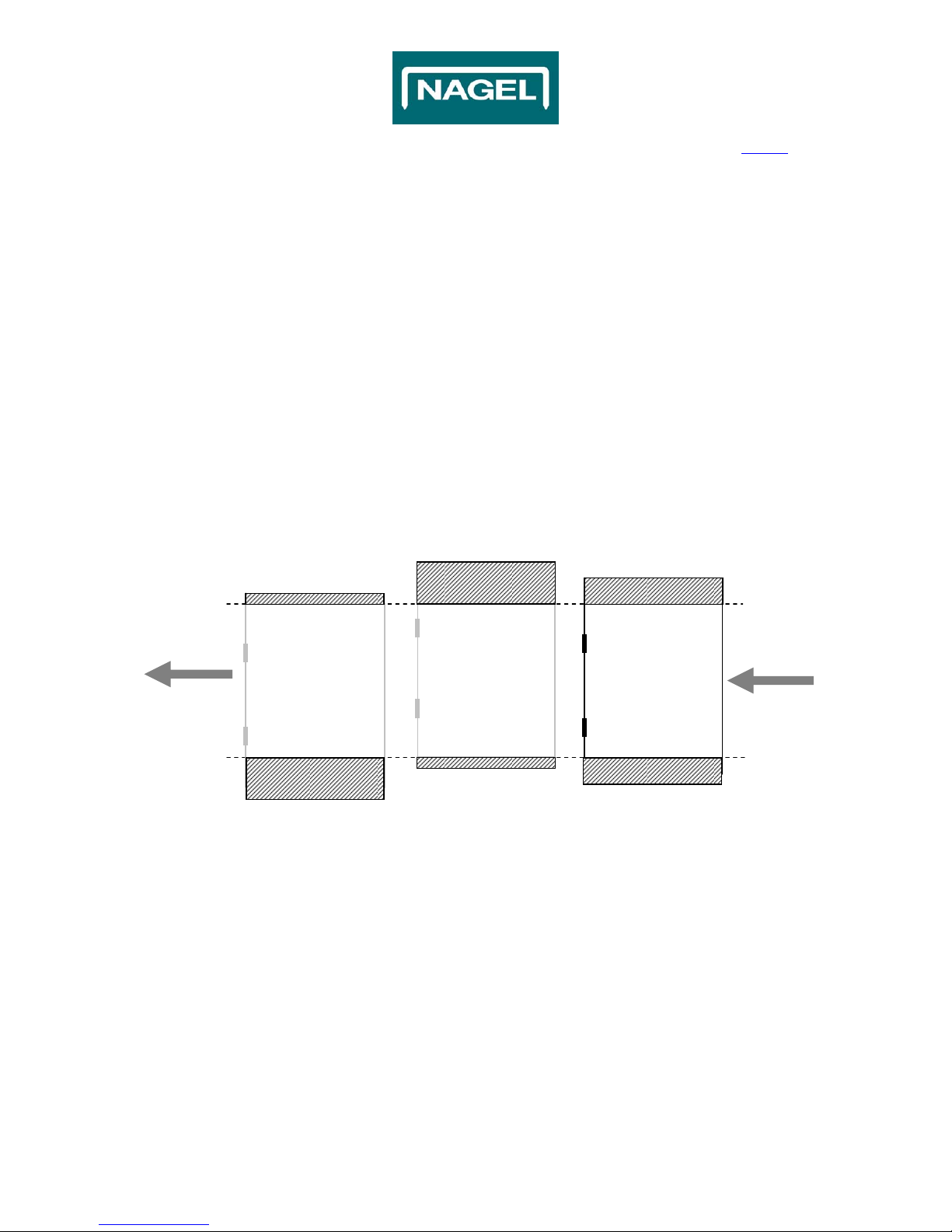
For example, in the schedule mentioned below (Fig. 2.1) is schematically rendered some results which are
possible with the STR by using a different Centre Offset (symmetrical or asymmetrical):
Fig. 2.1
Centre Offset:
15mm
Centre Offset:
-
15mm
Centre Offset:
0mm
33,5mm Waste
33,5mm Waste
3,5mm Waste 18,5mm Waste
3,5mm Waste
Finished Size:
260.0
mm
Infeed Size:
2
9
7.
0
mm
18,5mm Waste
© Ernst Nagel GmbH 2S Trimmer Service Manual en.doc Rev.1.0. 20.07.2011
7
Contents
2. General (continued)
2.1 Basic Information (continued)
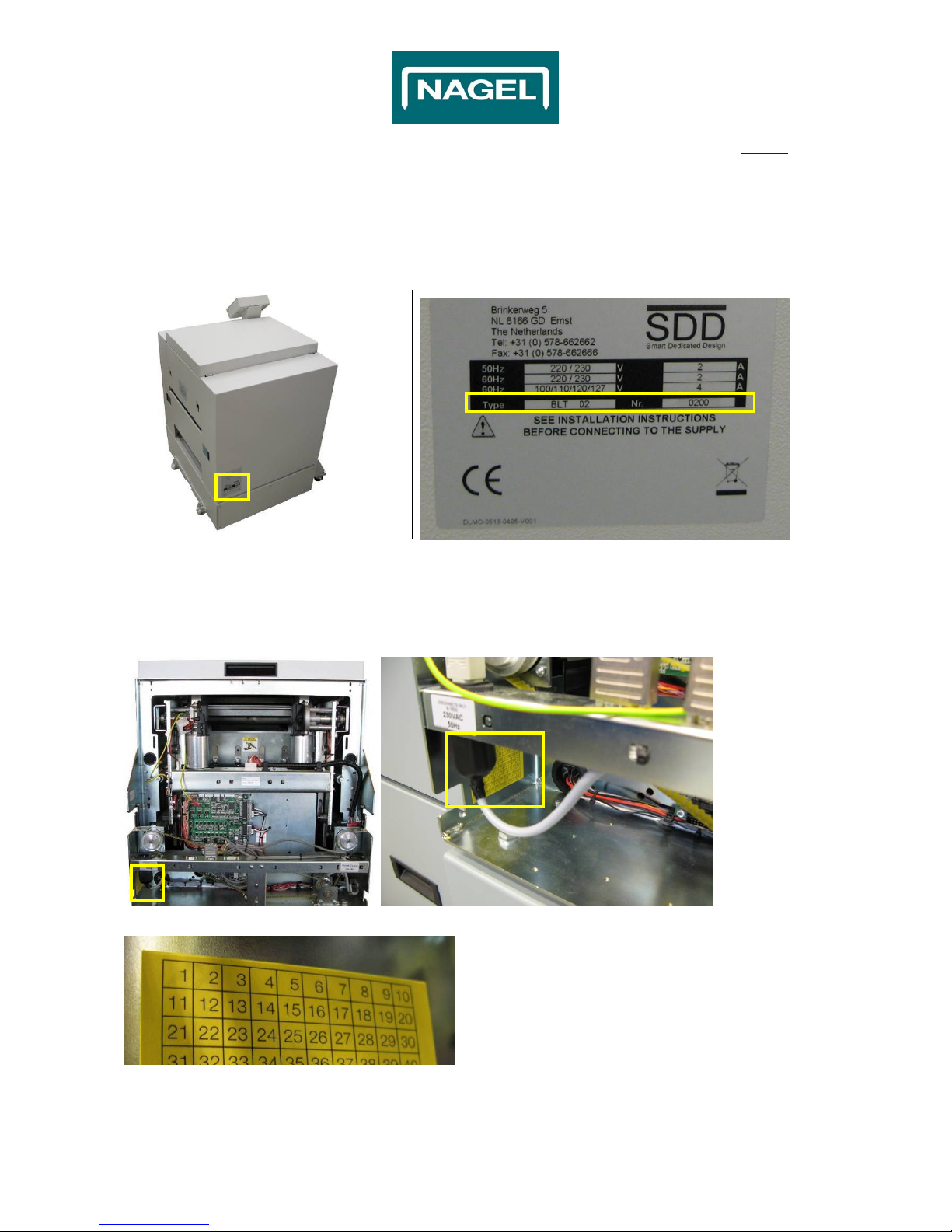
2.1.1 Type of machine and TAG
It is important to identify the type of machine and state (TAG) of it before carry out servicing activities.
At the Rear cover there is a label which refers to the Type of machine and serial Nr. (Fig. 1.1 & 1.2).
Fig. 1.1 Fig. 1.2
To find out if it is a TAG0, TAG1 or a TAG2 etc. Machine, find the Yellow Square label (Fig. 2.2 & 2.3).
The number that is marked on this label (Fig. 2.4) indicates the type (TAG) of the machine.
If nothing is marked, the type of machine is a TAG0.
Use only the appropriate settings/procedure for the type of machine!
Fig. 2.2 Fig. 2.3
Fig. 2.4
XX
X
X
X
X
© Ernst Nagel GmbH 2S Trimmer Service Manual en.doc Rev.1.0. 20.07.2011
8
Contents
2. General (continued)
2.2 Getting to know the STR
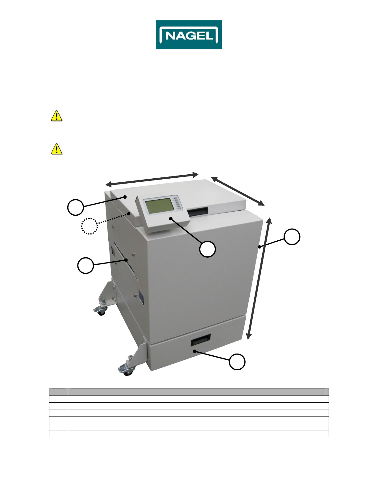
2.2.1 Main components overview
The pictures of the STR in this document can be different than the actual machine!
See the picture below to get familiar with the components of the STR (Fig. 2.5).
All direction are seen from the paper flow direction.
No. Action
1 Top Cover
2 Booklet Infeed
3 Trim Waste Bin
4 Power switch (inside)
5 User Interface (UI)
6 Booklet Outfeed
Rea
r
Front
Left
Right
To
p
Bottom
1
3
2
4
Fig. 2.5
5
6
© Ernst Nagel GmbH 2S Trimmer Service Manual en.doc Rev.1.0. 20.07.2011
9
Contents
2. General (continued)
2.2 Getting to know the STR (continued)
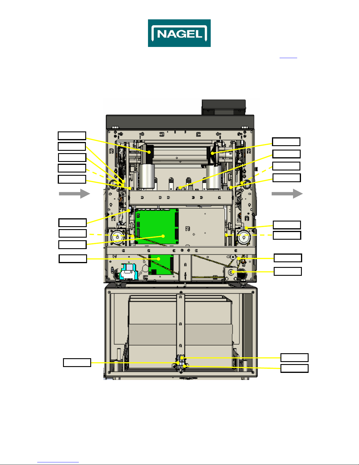
2.2.2 Components overview Inside
Fig. 2.7
Infeed Outfeed
Motor6
J5/P5
S2
PCB6
FC1
FC3
J9/P9
J-Motor3
J7/P7
Motor4
Motor3
S12
J4/P4
S1
J3/P3
Front-view
PCB = print board J-Motorx = Motor conn. Position Sx = Switch position
Jx/Px = Connector position FCx = Sensor position Motorx = Motor position
PCB5
J-Motor4
S7 S8
S9
© Ernst Nagel GmbH 2S Trimmer Service Manual en.doc Rev.1.0. 20.07.2011
10
Contents
2. General (continued)
2.2 Getting to know the STR (continued)
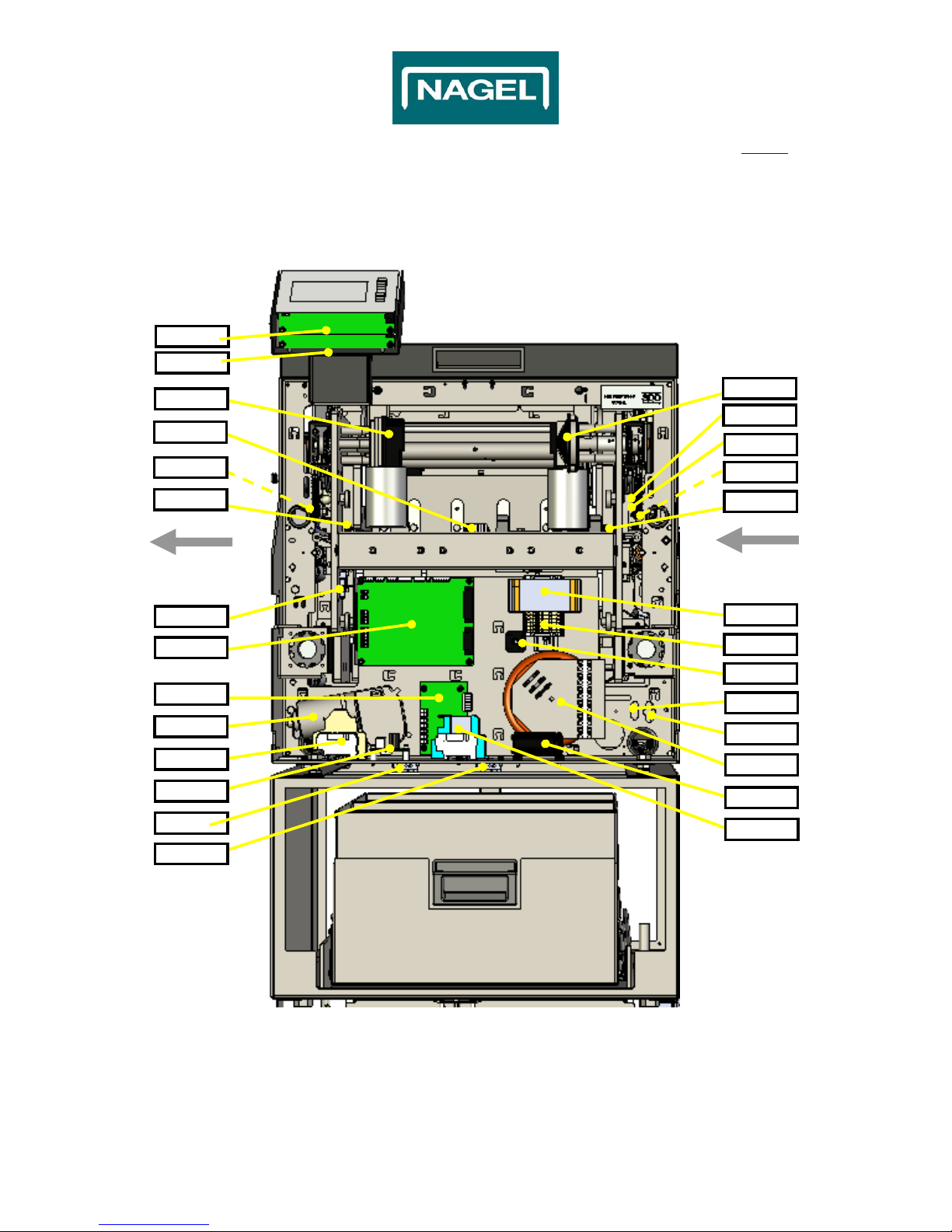
2.2.2 Components overview Inside
Fig. 2.8
Front-view
Outfeed Infeed
J2/P2
J1/P1
PCB2
FC3
PCB3
J-Motor2
FC1
J-Motor1
J6/P6
Motor2
Motor1
S10
PCB1 TR1
Trafo1
Motor5
TR13
PCB4 C1
FC7 K1+K2
DB1
J9/P9
J4/P4
PCB8
PCB7
PCBx = Printboard position J-Motorx = Motor conn. Position TRx = Terminal Rail
Jx/Px = Connector position FCx = Sensor position DBx = Rectifier position
Sx = Switch position Motorx = Motor position Cx = Capacitor postion
Trafox = Transformer position Kx = Relais position
FC4
Otros manuales para 2S Trimmer
2
Tabla de contenidos
Otros manuales de Recortadora de Nagel


