NAD M4 Manual de usuario

SERVICEMANUAL
SERVICE MANUAL
M4 C/AH
NAD ELECTRONICSINTERNATIONAL
TORONTO
M4 C/AH
FM/AM/DAB/XM TUNER
M4 C/AH
M4
STEREO
FM/AM/DAB/XM TUNER
STEREO
FM/AM/DAB/XM TUNER
STEREO
©NAD 2009

CONTENTS
SECTION 1 . . . .SUMMARY
SECTION 2 . . . .CABINET & MAIN CHASSIS
SECTION 3 . . . .ELECTRICAL
SECTION 4 . . . .REPLACEMENT PARTS LIST

SECTION 1
SUMMARY
CONTENTS
PRODUCT SAFETY SERVICING GUIDELINES FOR AUDIO PRODUCTS
............. 1-2
SERVICING PRECAUTIONS ...........................................................................1-3
• General Servicing Precautions
• Insulation Checking Prodedure
• Electrostatically Sensitive Devices
SPECIFICATIONS ........................................................................................... 1-4,5
1-1

1-2
SUBJECT: GRAPHIC SYMBOLS
PRODUCT SAFETY SERVICING GUIDELINES FOR AUDIO PRODUCTS
A.C. VOLTMETER
GOOD EARTH GROUND
SUCH AS THE WATER
PIPE. CONDUIT. ETC
PLACE THIS PROBE
ON EACH EXPOSED
METAL PART
CAUTION : DO NOT ATTEMPT TO MODIFY THIS
PRODUCT IN ANY WAY, NEVER PERFORM CUSTOM-
IZED INSTALLATIONS WITHOUT MANUFACTURER’S
APPROVAL. UNAUTHORIZED MODIFICATIONS WILL
NOT ONLY VOID THE WARRANTY, BUT MAY LEAD TO
YOUR BEING LIABLE FOR ANY RESULTING PROP-
ERTY DAMAGE OR USER INJURY.
SERVICE WORK SHOULD BE PERFORMED ONLY
AFTER YOU ARE THOROUGHLY FAMILIAR WITH ALL
OF THE FOLLOWING SAFETY CHECKS AND SERVIC-
ING GUIDELINES. TO DO OTHERWISE,INCREASES
THE RISK OF POTENTIAL HAZARDS AND INJURY TO
THE USER.
WHILE SERVICING, USE AN ISOLATION TRANS-
FORMER FOR PROTECTION FROM A.C. LINESHOCK.
SAFETY CHECKS
AFTER THE ORIGINAL SERVICE PROBLEM HAS
BEEN CORRCTED. A CHECK SHOULD BE MADE OF
THE FOLLOWING.
SUBJECT : FIRE & SHOCK HAZARD
1.BE SURE THAT ALL COMPONENTS ARE POSI-
TIONED IN SUCH A WAY AS TO AVOID POSSIBILITY
OF ADJACENT COMPONENT SHORTS.THIS IS ESPE-
CIALLY IMPORTANT ON THOSE MODULES WHICH
ARE TRANSPORTED TO AND FROM THE REPAIR
SHOP.
2. NEVER RELEASE A REPAIR UNLESS ALL PROTEC-
TIVE DEVICES SUCH AS INSULATORS, BARRIERS,
COVERS, SHIELDS, STRAIN RELIEFS, POWER
SUPPLY CORDS, AND OTHER HARDWARE HAVE-
BEEN REINSTALLED PER ORIGINAL DESIGN. BE
SURE THAT THE SAFETY PURPOSE OF THE POLAR-
IZED LINE PLUG HAS NOT BEEN DEFEATED.
3. SOLDERING MUST BE INSPECTED TO DISCOVER
POSSIBLE COLD SOLDER JOINTS, SOLDER
SPLASHES OR SHARP SOLDER POINTS. BE CER-
TAIN TO REMOVE ALL LOOSE FOREIGN PARTICLES.
4. CHECK FOR PHYSICAL EVIDENCE OF DAMAGE
OR DETERIORATION TO PARTS AND COMPONENTS.
FOR FRAYED LEADS, DAMAGED INSULATION
(INCLUDING A.C. CORD). AND REPLACE IF NECES-
5. NO LEAD OR COMPONENT SHOULD TOUCH A
RECIVING TUBE OR A RESISTOR RATED AT 1 WATT
OR MORE. LEAD TENSION AROUND PROTRUNING
METAL SURFACES MUST BE AVOIDED.
6. ALL CRITICAL COMPONENTS SUCH AS FUSES,
FLAMEPROOF RESISTORS, CAPACITORS, ETC.
MUST BE REPLACED WITH EXACT FACTORY TYPES,
DO NOT USE REPLACEMENT COMPONENTS OTHER
THAN THOSE SPECIFIED OR MAKE UNRECOM-
MENDED CIRCUIT MODIFICATIONS.
7. AFTER RE-ASSEMBLY OF THE SET ALWAYS PER-
FORM AN A.C. LEAKAGE TEST ON ALL EXPOSED
METALLIC PARTS OF THE CABINET, (THE CHANNEL
SELECTOR KNOB, ANTENNA TERMINALS. HANDLE
AND SCREWS) TO BE SURE THE SET IS SAFE TO
OPERATE WITHOUT DANGER OF ELECTRICAL
SHOCK. DO NOT USE A LINE ISOLATION TRANS-
FORMER DURING THIS TEST USE AN A.C. VOLTME-
TER, HAVING 5000 OHMS PER VOLT OR MORE SEN-
SITIVITY, IN THE FOLLOWING MANNER; CONNECT A
1500 OHM 10 WATT RESISTOR, PARALLELED BY A
.15 MFD. 150.V A.C TYPE CAPACITOR BETWEEN A
KNOWN GOOD EARTH GROUND (WATER PIPE,
CONDUIT,ETC.) AND THE EXPOSED METALLIC
PARTS, ONE AT A TIME. MEASURE THE A.C. VOLT-
AGE ACROSS THE COMBINATION OF 1500OHM
RESISTOR AND .15 MFD CAPACITOR. REVERSE THE
A.C. PLUG AND REPEAT A.C. VOLTAGE MEASURE-
MENTS FOR EACH EXPOSED METALLIC PART. VOLT-
AGE MEASURED MUST NOT EXCEED 75 VOLTS
R.M.S. THIS CORRESPONDS TO 0.5 MILLIAMP A.C
ANY VALUE EXCEEDING THIS LIMIT CONSTITUTES A
POTENTIAL SHOCK HAZARD AND MUST BE COR-
RECTED IMMEDIATELY.
THE LIGHTNING FLASH WITH APROWHEAD SYMBOL. WITHIN AN EQUILATERAL TRIANGLE, IS INTENDED
TO ALERT THE SERVICE PERSONNEL TO THE PRESENCE OF UNINSULATED “DANGEROUS VOLTAGE”
THAT MAY BE OF SUFFICIENT MAGNITUDE TO CONSTITUTE A RISK OF ELECTRIC SHOCK.
THE EXCLAMATION POINT WITHIN AN EQUILATERAL TRIANGLE IS INTENDED TO ALERT THE SERVICE
PERSONNEL TO THE PRESENCE OF IMPORTANT SAFETY INFORMATION IN SERVICE LITERATURE.

SERVICING PRECAUTIONS
CAUTION:Before servicing the Stereo Tuner covered by
this service data and its supplements and addends, read and
follow the SAFETY PRECAUTIONS. NOTE: if unforeseen
circumstances create conflict between the following servicing
precautions and any of the safety precautions in this publication,
always follow the safety precautions.
Remember Safety First:
General Servicing Precautions
1. Always unplug the Stereo Tuner AC power cord from the AC
power source before:
(1) Removing or reinstalling any component, circuit board,
module, or any other assembly.
(2) Disconnecting or reconnecting any internal electrical
plug or other electrical connection.
(3) Connecting a test substitute in parallel with an electrolytic
capacitor.
Caution: A wrong part substitute or incorrect polarity
installation of electrolytic capacitors may result in an
explosion hazard.
2. Do not spray chemicals on or near this Stereo Tuner or a-
ny of its assemblies.
3. Unless specified otherwise in this service data, clean
electrical contacts by applying an appropriate contact
cleaning solution to the contacts with a pipe cleaner,
cottontipped swab, or comparable soft applicator.
Unless specified otherwise in this service data, lubrication
of contacts is not required.
4. Do not defeat any plug/socket B+ voltage interlocks with
which instruments covered by this service manual might be
equipped.
5. Do not apply AC power to this Stereo Tuner and/or any of its
electrical assemblies unless all solid-state device heat sinks
are correctly installed.
6. Always connect test instrument ground lead to the
appropriate ground before connecting the test instrument
positive lead. Always remove the test instrument ground lead
last.
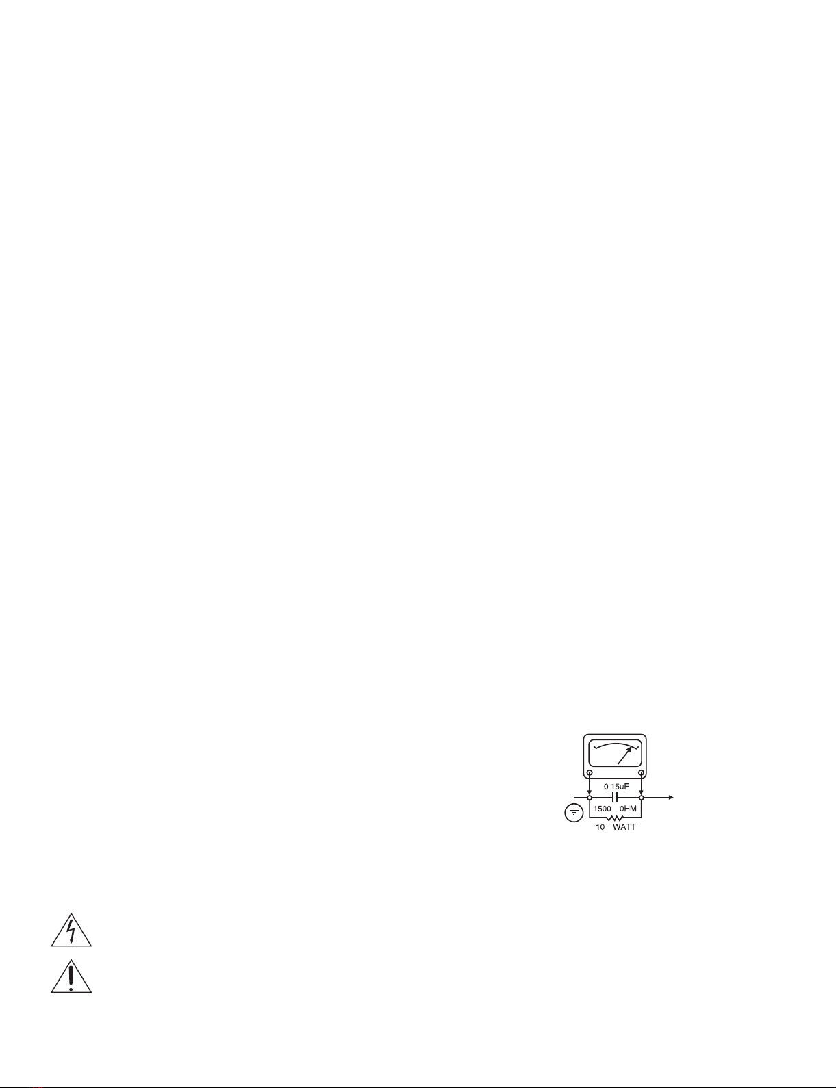
Insulation Checking Procedure
Disconnect the attachment plug from the AC outlet and turn the
power on. Connect an insulation resistance meter (500V) to the
blades of the attachment plug. The insulation resistance
between each blade of the attachment plug and accessible
conductive parts (Note 1) should be more than 1 M-ohm.
Note 1: Accessible Conductive Parts including Metal panels,
Input terminals, Earphone jacks, etc.
Electrostatically Sensitive (ES) Devices
Some semiconductor (solid state) devices can be damaged
easily by static electricity. Such components commonly are
called Electrostatically Sensitive (ES) Devices. Examples of
typical Es devices are integrated circuits and some field effect
transistors and semiconductor chip components.
The following techniques should be used to help reduce the
incidence of component damage caused by static electricity.
1. Immediately before handing any semiconductor component
or semiconductor-equipped assembly, drain off any
electrostatic charge on your body by touching a known earth
ground. Alternatively, obtain and wear a commercially
available discharging wrist strap device, which should be
removed for potential shock reason prior to applying power to
the unit under test.
2. After removing an electrical assembly equipped with ES
devices, place the assembly on a conductive surface such as
aluminum foil, to prevent electrostatic charge buildup or
exposure of the assembly.
3. Use only a grounded-tip soldering iron to solder or unsolder
ES devices.
4. Use only an antistatic solder removal device. Some solder
removal devices not classified a “anti-static” can generate
electrical charges sufficient to damage ES devices.
5. Do not use freonpropelled chemicals. These can generate
electrical charge sufficient to damage ES devices.
6. Do not remove a replacement ES device from its protective
package until immediately before you are ready to install it.
(Most replacement ES devices are packaged with leads
electrically shorted together by conductive foam, aluminum
foil, or comparable conductive material).
7. Immediately before removing the protective material from the
leads of a replacement ES device, touch the protective
material to the chassis or circuit assembly into which the
device will be installed.
Caution: Be sure no power is applied to the chassis or circuit,
and observe all other safety precautions.
8.Minimize bodily motions when handing unpackaged
replacement ES devices. (Normally harmless motion such as
the brushing together of your clothes fabric or the lifting of
your foot from a carpeted floor can generate static electricity
sufficient to damage an ES device.)
1-3

AM TUNER SECTION
Usable Sensitivity (999/1000kHz) 30dBμ
S/N Ratio (5mV in) 38dB
THD (5mV in) <3%
IF Rejection (450kHz) >36dB
Image Rejection (F+2xIF) 28dB
Selectivity 17dB
Output 130mV ±20mV
Loop Sensitivity (20dB S/N)
999/1000 kHz 66 dB
603/600 kHz 66 dB
1404/1400 kHz 66 dB
Frequency response (100-2.3kHz,5mV) ±6dB
FM TUNER SECTION
Usable Sensitivity (98MHz) 6dBμ
Signal / Noise Ratio Mono 72 dB
(60 dBμ, IHF wtd) Stereo >66 dB
Frequency Response
(20 Hz - 15 kHz, 60 dBμ) ±1.0 dB
Channel Separation (60 dBμ)
30Hz >33dB
1kHz >42dB
10kHz >35dB
Alternate Channel Sensitivity
(40 dBμ, ±400 kHz) 60 dB
Capture Ratio (40 dBμ) 1.5 dB
AM Suppression
(60 dBμ, 100% Mod.FM, 30% Mod.AM) 65 dB
Image Rejection (119.4MHz) 85dB
I.F. Rejection (10.7MHz) 80dB
Pilot Suppression (60dBμ) 60dB
THD (60 dBμ, L=R 75 kHz for North America version; 40 kHz
deviation for Europe version)
1-4
SPECIFICATIONS

Mono 0.20%
Stereo 0.25%
Auto-Search
Sensitivity On 24dBμ
SensitivityOff 15dBμ
RDS Decode Sensitivity 25dBμ
DAB SECTION
Band lll 174MHz-240MHz
Input 50 Ohm, nominal
Max signal ~-3dBm
Sensitivity ~-96dBm
Adjacent Channel Rejection ~ 35dB
Display 2-line by 16-character
DOT Matrix
Audio Output Stereo 2.5Vp-p
48kHz sample rate 16 bit sample Resolution
Optical S/PDIF IEC60958 Compliant
48kHz sample rate 24 bit sample resolution
1-5

2-1
SECTION 2
CABINET & MAIN CHASSIS
CONTENTS
EXPLODED VIEWS.................................................................................. 2-2
1. Cabinet and main frame section...................................................................2-2
2. Packing accessory section ... .......................................................................... 2-3
3. Exploded view parts list.. ... ... ......................................................................... 2-4

6
6
)
)
)
)
)
)
)
)
6
)
)
)
)
)
)
)3
7
&
&
&&
&
5
5
)
)
7
7
)
6
6
6
6
6
6
;'
6
6
6
6
6
6
6
6
&
;'
6
6
6
&
M4 EXPLODED VIEWS
2-2

AC Cord
DAB Antenna
Shipping Box
Gift Box
polyfoam(down)
Polyfoam(up)
Batteries
Accessory Box
REMOCON
AM Antenna
M4 Packing Accessory Section
2-3
Otros manuales para M4
2
Este manual sirve para los siguientes modelos
1
Tabla de contenidos
Otros manuales de Sintonizador de NAD


